Table of Contents
Advertisement
Advertisement
Table of Contents

Subscribe to Our Youtube Channel
Related Manuals for Antec GX700

Summary of Contents for Antec GX700
- Page 1 User GX700 Manual...
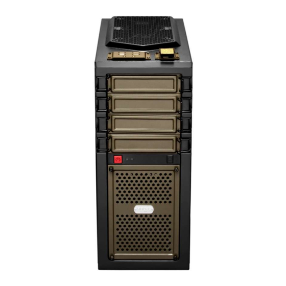
- Page 2 GX700 User Manual Congratulations on your purchase of the GX700! The new flagship in Antec’s GX series, the GX700 is ready to take your system to the next level. Builders can now assemble and expand faster with tool-less drive bays and customizable HDD trays. This boldly designed gaming enclosure features metal clasps and rugged drive bay covers.
-
Page 3: Table Of Contents
Table of Contents Section 1: Introduction Getting to Know Your Chassis ................5 Chassis Specifications..................6 Included Screws ....................6 Before You Begin ....................7 Section 2: Hardware Installation Setting Up ......................10 Removing the Front Bezel………………………………………………………………………………11 Motherboard Installation................... 11 Power Supply Installation .................. -
Page 4: Section 1: Introduction
Section 1 Introduction... -
Page 5: Getting To Know Your Chassis
GX700 User Manual Getting to Know Your Chassis... -
Page 6: Chassis Specifications
Standard ATX, microATX, Mini-ITX Top I/O Panel 2 x USB 3.0 2x USB 2.0 Audio In/Out Fan controller - Power and Reset buttons located at the front of the chassis *The top dive bay of the GX700 is only meant for controls... -
Page 7: Included Screws
Included Screws An inventory of all screws and intended usage and quantity is provided here: A. PSU screws B. Motherboard standoffs C. Motherboard and fan screws D. Zip ties... -
Page 8: Before You Begin
Before You Begin In order to ensure that your building experience with the GX700 will be a positive one, please take note of the following: While working inside your GX700, keep your chassis on a flat, stable surface. Make sure your build environment is clean, well-lit, and free of dust. -
Page 9: Section 2: Hardware Installation
Section 2 Hardware Installation... -
Page 10: Setting Up
GX700 User Manual Setting Up Put the case upright on a flat, stable surface so that the rear panel (power supply and expansion slots) is facing you. To remove the left and right side panels, remove each of the two thumbscrews, and then slide the side panel towards you. -
Page 11: Removing The Front Bezel
Check the manual of your CPU cooler to find out if there are steps you must do before installing the motherboard. The GX700 does not come include an I/O panel. Your motherboard should include an I/O panel, if not please contact your motherboard manufacturer for the correct I/O panel. - Page 12 The GX700 comes with motherboard standoffs (B in section 1.3). These are meant to be positioned for Standard ATX, microATX or Mini-ITX motherboards and can be relocated to accommodate various form factors. 1. Lay the case down so that the open side is up.
-
Page 13: Power Supply Installation
Power Supply Installation 1. With the case upright, place the power supply in the case and align the rear of the unit with the mounting holes. 2. Attach the power supply to the case with the screws provided (A). Attach the power supply with the provided screws... -
Page 14: External 5.25" Device Installation
External 5.25” Device Installation 1. Remove the metal drive bay cover by unlocking the click-on clasps Remove the metal drive bay cover 2. Pull out the drive bay tabs on either side by twisting the locking mechanism to the vertical position Pull out the drive bay tab on both sides... - Page 15 3. Slide your 5.25” drive through the front of the chassis until it lines up flush with the front bezel. Slide you drive in until it is flush with the bezel 4. Replace the drive bay tab the by aligning its pins with the holes on your 5.25” drive, then lock it into place by turning the locking mechanism to the horizontal position.
-
Page 16: Internal 3.5" Device Installation
Internal 3.5” Device Installation The GX700 includes 5 drive holders. You will need one for each 3.5” drive. 1. Insert three pins on the drive holder into three holes on the side of your 3.5” drive. 2. Slightly bend the drive holder to snap the drive into place. -
Page 17: Internal 2.5" Device Installation
Internal 2.5” Device Installation Each of the five 3.5” drive bays also support 2.5” drives: 1. Align your 2.5” drive with the holes of the drive holder 2. Secure your drive with the 2.5” screws provided (C in Section 1.3) 3. -
Page 18: Cable Management
Cable Management There is a cable management compartment between the motherboard and right side panel, as well as cable ties located on the back of the motherboard panel. You can tuck excess cables in this compartment or route them to the drive bays. Choose the cables you would like to pass through the holes behind the motherboard tray. -
Page 19: Section 3: Cooling System
Section 3 Cooling System... -
Page 20: Included Fans
GX700 User Manual Included Fans The GX700 comes with two standard 140 mm fans and a rear 120 mm fan (yellow outline). The red rectangles indicate additional fan mounts. Mounting procedures for these fans are discussed in Section 3.2. -
Page 21: Optional Fans
Optional Fans The GX700 includes mounts for up to three more fans. These mounts are as follows: - Optional 2 x 120 mm front intake fans - Optional 1 x 120 mm side fan to cool graphic cards Front intake 120 mm fans You can install these fans using the screws provided (C in Section 1.3). -
Page 22: Air Filters
Air Filters There are two filters in the GX700 that can be removed and cleaned: the front filter and the PSU intake filter. You can access the front filter by removing the metal filter panel and pushing down on the tabs at... - Page 23 To remove the front air filter: 1. Remove the four thumbscrews and metal filter panel Remove four thumbscrews Remove the metal panel 2. Push down on the tab on the filter and pull it away from the inside of the bezel. Push down on the filter tab before attempting to pull it away.
- Page 24 The GX700 features a removable PSU filter. To remove the PSU filter: Remove the filter by pulling the tab toward you using the tab outside the chassis. Pull the filter toward you using the tab outside the chassis.
- Page 25 US &Canada www.antec.com 1-800-22ANTEC (US) nasupport@antec.com Europe +31-(0)10-4622060 (EU) eusupport@antec.com +886 (0)800-060-696 apsupport@antec.com © Copyright 2013 Antec, Inc. All rights reserved. All trademarks are the property of their respective owners. Reproduction in whole or in part without written permission is prohibited.
Need help?
Do you have a question about the GX700 and is the answer not in the manual?
Questions and answers