
Subscribe to Our Youtube Channel
Related Manuals for peerless-AV HD Flow HDS200

Summary of Contents for peerless-AV HD Flow HDS200
- Page 1 User Manual and Installation Guide Pro Wireless Multimedia Kit Models: HDS200 HDS200-2 HDS200-3 ® HDS200-4 R E ADY ISSUED: 07-24-12 SHEET #: 180-9023-1...
-
Page 3: Table Of Contents
Contents Safety Precautions ............................4 Proper Care and Safety ............................4 Unit Care Recommendations ..........................4 Introduction ...............................5 Features .................................5 Package Contents ............................5 Product Specifi cations.............................6 Video Format Supported ..........................7 Audio Format Supported ..........................7 Wireless Connection ............................7 WiFi Channel Frequencies ..........................7 Transmitter ..............................8 Receiver ...............................12 Remote Control ............................16 Installation and Operation ..........................19... -
Page 4: Safety Precautions
Keep the battery of remote control out immediately unplug the product and of reach of children. call Peerless-AV Customer Care at 1-800-865-2112. Do not attempt to open the outer case of the Transmitter or Receiver. Doing Keep the remote control away from so will void the product warranty. -
Page 5: Hds200
© 2012 Peerless Industries, Inc. Peerless-AV™ is a trademark of Peerless Industries, Inc. All rights reserved. HD Flow™ is a trademark of I Do It, LTD. Other parties’ marks are the property of their respective owners. hdflow.com... -
Page 6: Product Specifi Cations
Product Specifi cations HDS200 Models 2 x HDMI up to 1080p (60Hz) Video Input (Transmitter) 1 x Composite 1 x YPbPr Component 1 x HDMI up to 1080p (60Hz) Video Output (Receiver) 1 x Composite 1 x YPbPr Component H.264 Baseline Profile with Level 4.2... -
Page 7: Video Format Supported
Video Format Supported • Digital Video º HDMI - Up to 1080p @ 24Hz, 25Hz, 30Hz, 50Hz, 60Hz • Analog Video º Composite – 480i @ 60Hz, 70Hz, 85Hz º Component – 1080i @ 50Hz, 60Hz, 720p @ 50Hz, 60Hz º... -
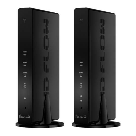
Page 8: Transmitter
Transmitter Transmitter Front ISSUED: 07-24-12 SHEET #: 180-9023-1 8 of 36... - Page 9 Transmitter Front 1. Power/Link Indicator Light • Blinking indicator light - System booting or establishing link between the Transmitter and the Receiver. • Quick blinking indicator light - Software upgrading or wireless/LAN mode switching. • Solid indicator light - Link between the Transmitter and Receiver has been established and is ready for signal transmission.
- Page 10 Transmitter Back ISSUED: 07-24-12 SHEET #: 180-9023-1 10 of 36...
- Page 11 Transmitter Back 1. HDMI 1 IN • HDMI1 input port 2. HDMI 2 IN • HDMI2 input port 3. AV-IN • Composite input port 4. IR-OUT • Connects IR Flasher to the Transmitter for remote control of external devices which are connected to the Transmitter (i.e.
-
Page 12: Receiver
Receiver Receiver Front ISSUED: 07-24-12 SHEET #: 180-9023-1 12 of 36... - Page 13 Receiver Front 1. Power/Link • Blinking indicator light - System booting or establishing link between the Transmitter and the Receiver. • Rapid blinking indicator light - Software upgrading or wireless/LAN mode switching. • Solid indicator light - Link between the Transmitter and Receiver has been established and is ready for signal transmission.
- Page 14 Receiver Back ISSUED: 07-24-12 SHEET #: 180-9023-1 14 of 36...
- Page 15 Receiver Back 1. HDMI-OUT • HDMI output port 2. AV-OUT • Composite output port 3. IR-IN • Connects the IR Extender in order to extend IR reception range. 4. AUDIO-OUT* • Stereo audio output port 5. COMPONENT-OUT* 6. USB • USB port is used for fi...
-
Page 16: Remote Control
Remote Control 1. POWER Button - Turns the Transmitter and Receiver power ON/OFF. • ON: If the Transmitter and Receiver are powered off and the Power/Link Indicator Light is on, press the power button pointed at either unit to turn on both unit's at the same time (this will take about 30 seconds). - Page 17 3. VIDEO OUT (Receiver) - Selects the Audio/Video output port of the Receiver. HDMI - Selects HDMI as the Audio/Video output. • Component - Selects Component as the Audio/Video output. • AV - Selects AV as the Audio/Video output. • Note: Remote must be pointing at the Receiver directly to control its output settings.
- Page 18 Installing the Remote Control Battery The battery slip is located on the bottom of the remote control. Step 1 Push the tab, located on the left of the battery slip, to the right and pull out the slip. Battery Slip Tab Battery Slip Step 2 Place the battery into the slip, positive (+) end facing up as shown.
-
Page 19: Installation And Operation
Installation and Operation Before starting the installation, please ensure that all source components (Blu-ray player, cable box, etc.) and the display equipment (TV, display, projector, etc.) are turned off. Step 1 Connecting Source Components To The Transmitter A. HDMI Media Source •... - Page 20 D. Component Media Source • Video – Connect the Component Video output (YPbPr) from the source, into to the Component Adapter (included). Connect the Component Adapter to the PC-IN port on the Transmitter. • Audio - Connect a 3.5mm-to-RCA stereo audio cable (not included) from the media source’s audio output to the PC AUDIO-IN input port on the Transmitter.
- Page 21 Step 3 Connecting the Receiver to the Display Device Note: Connect the Receiver to the display device using the port with the high resolution capability, HDMI port is preferred. Regardless of the number of analog or digital sources connected to the Transmitter, only one port is required to be connected to the display.
- Page 22 While turning on the display device, the HD Flow Pro Wireless Multimedia Kit will be going through the start up process. The process takes about 1.5 to 2 minutes to complete. The Power/Link Indicator Light on the Transmitter and the Receiver should be fl ashing at fi rst. Flashing indicates that that the units are establishing a secure connection.
-
Page 23: Selecting Input And Output Port
Selecting Input and Output Port There are two ways to select input and output sources on the HD Flow Transmitter and Receiver: 1. Using the provided Remote • Transmitter - Press the desired input while pointing the remote at the Transmitter unit. •... -
Page 24: Lan Connection Through Router (Lan One-To-One)
Notes: We recommend that you disconnect and then re-connect the LAN cable to ensure LAN operation. Once video and audio come back up, the process is complete. To return the units back to WiFi mode press the WiFi Channel 1 button for 5 seconds in front of the Receiver until all the indicator lights start fl... -
Page 25: Indicator Lights Decoded
Step 5 Under the heading “Streaming I/F” use the pull down menu to change WiFi to LAN. Step 6 Enter the proper IP address, for the unit being set up, based on the network's domain. Step 7 Once all the settings have been entered click the Submit button at the bottom of the form. Keep clicking on the Submit button until you see confi... -
Page 26: Ir Flasher
Peer-To-Peer Wireless Mode Peer-to-Peer Wireless Mode is a pre-confi gured setting that enables one Transmitter to stream AV media to one Receiver. HDS200 model HD Flow Pro Wireless Multimedia Kit comes pre-confi gured for Peer-to-Peer Wireless mode. Peer-To-Peer LAN (wired) Mode Peer-to-Peer LAN (wired) Mode is an available confi... -
Page 27: Multicast Modes
To set up the HD Flow Pro Wireless Multimedia Kit as a multicast system that transmits to 2, 3 or 4 Receivers using the LAN Confi guration Method please reference the instruction manual that comes with the HDS200-R or visit http://www.hdfl ow.com/Tech-Support to download instructions. -
Page 28: Faqs
FAQs What compression standard does the HD Flow use to stream Full HD 1080p content? A. H.264 Baseline Profi le Level 4.2 video compression. Does HD Flow Pro Wireless Multimedia Kit deliver 5.1 audio? A. No, the HD Flow Pro Wireless Multimedia Kit only outputs 2-channel audio at the Receiver. What do I use the VGA Adapter for? A. - Page 29 Can the HD Flow Pro Wireless Multimedia Kit be set to default to a specifi c input/output if the unit is turned off or power is lost? A. Yes, the HD Flow Pro Wireless Multimedia Kit can be set to desired input and output ports via a programming page that can be accessed by using LAN programming.
-
Page 30: Appendix
Appendix Factory Reset CAUTION Factory reset will revert all settings to factory defaults. It is not recommended to perform factory reset on multicast systems (systems that have two or more Receivers). If there are issues with multicast systems, please reference http://www.hdfl ow.com/Tech-Support or call Technical Support at 1-800-865-2112. - Page 31 How to Check Firmware Version Step 1 Connect the Receiver that needs its fi rmware to be checked to the display device (reference the installation section of this manual). Step 2 Plug in the power AC adapter into a power outlet, and then connect the power cord to the HD Flow Pro Wireless Multimedia Kit and turn on the display device.
- Page 32 Supported Video Formats HD Flow Transmitter HD Flow Receiver Video Standard Resolution HDMI D Sub AV(CVBS) HDMI COMP AV(CVBS) 640 x 480p60 640 x 480p70 640 x 480p85 800 x 600p60 800 x 600p70 800 x 600p85 1024 x 768p60 1024 x 768p70 1024 x 768p85 1152 x 864p60...
- Page 33 FCC Compliance This equipment has been tested and found to comply with the limits for a Class B digital device, pursuant to part 15 of the FCC Rules. These limits are designed to provide reasonable protection against harmful interference in a residential installation. This equipment generates, uses, and can radiate radio frequency energy and, if not installed and used in accordance with the instruction manual, may cause harmful interference to radio communications.
-
Page 34: Warranty
Warranty 1 YEAR LIMITED WARRANTY The HDS200 is distributed by Peerless Industries, Inc. using the highest quality components and technology available. The Product is warranted to be free from defects in material and workmanship, given normal use and care, for 1 Year from the original purchase date with proof of purchase. Please retain a copy of your receipt as you will need this to obtain warranty work. -
Page 35: Contact Information
Contact Information Customer Care Need help with installation or set up? Call Peerless-AV Customer Care 1-1-800-865-2112 (available 7:00am- 7:00pm CST, Monday - Friday), or email us at info@peerless-av.com. Peerless -AV 2300 White Oak Circle Aurora, IL 60502 USA www.hdfl ow.com... - Page 36 Aurora, IL 60502 USA 1-800-865-2112 www.peerless-av.com www.hdfl ow.com ©2012 Peerless-AV. All rights reserved. Peerless-AV is a trademark of Peerless Industries, Inc. HD Flow is a trademark of I Do It, LTD. Other parties’ marks are the property of their respective owners.
Need help?
Do you have a question about the HD Flow HDS200 and is the answer not in the manual?
Questions and answers