
Related Manuals for Sterling HE Series

Summary of Contents for Sterling HE Series
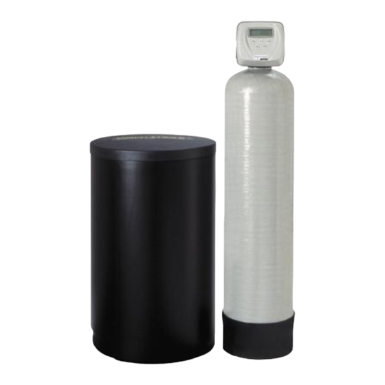
- Page 1 Installation Instructions & Owner's Manual HE Series 12630 US Highway 33 N. Churubusco, IN 46723 Phone: (260) 693-1972 Fax: (260)693-0602...
-
Page 2: Table Of Contents
TABLE OF CONTENTS: Preinstallation Instructions for Dealers Page 3 Bypass Valve Page 3-4 Installation Page 5-6 Programming Procedures for Water Softeners Page 7-8 Programming Procedures for Backwashing Filters Page 8-9 Operating Displays for Softeners & Backwashing Filters Page 10 Start-up Instructions Page 11 Troubleshooting Guide Page 12-13... -
Page 3: Preinstallation Instructions For Dealers
PREINSTALLATION INSTRUCTIONS FOR DEALERS: The manufacturer has set the water treatment unit's sequence of cycles, cycle times, salt dose, exchange capacity and gallon capacity. For water softeners, the salt dose refill time has been preset. For iron filters, the regeneration tank refill time has been preset. The dealer should read this page and guide the installer regarding hardness, day override, and time of regeneration, before installation: For the installer, the following must be used:... -
Page 4: Bypass Valve
1. Normal Operation Position: The inlet and outlet handles point in the direction of flow indicated by the engraved arrows on the control valve. Water flows through the control valve for normal operation of a water softener or filter. During the regeneration cycle this position provides regeneration water to the unit, while also providing untreated water to the distribution system (Fig. -
Page 5: Installation
INSTALLATION: GENERAL INSTALLATION & SERVICE WARNINGS The control valve, fittings and/or bypass are designed to accommodate minor plumbing misalignments. There is a small amount of "give" to properly connect the piping but the water softener is not designed to support the weight of plumbing. Do not use Vaseline, oils, other hydrocarbon lubricants or spray silicone anywhere. - Page 6 6. INLET/OUTLET PLUMBING: Be sure to install Bypass Valve onto main control valve before beginning plumbing. Make provisions to bypass outside hydrant and cold hard water lines at this time. Install an inlet shutoff valve and plumb to the unit's bypass valve inlet located at the right rear as you face the unit.
-
Page 7: Programming Procedures For Water Softeners
PROGRAMMING PROCEDURES FOR WATER SOFTENERS: 1. Set time of day: Time of day should only need to be set after extended power outages or when daylight saving time begins or ends. If an extended power outage occurs, the time of day will flash on and off indicating that the time should be reset. -
Page 8: Programming Procedures For Backwashing Filters
2. Programming cont'd: STEP 4 -- Regeneration Hour: The manufacturer has factory set 2:00 a.m. as the default. This is the hour of day for regeneration and can be reset by using buttons. "AM/PM" toggles after 12. The default time is 2:00 a.m. (recommended for a normal household). - Page 9 2. Programming: STEP 1 -- Press simultaneously for 3 seconds. NEXT STEP 2 -- Hardness: N/A (not available) for "filter" selection. Press to go to step 3. Press if you need to return to the previous step. NEXT REGEN STEP 3 -- Days Between Regeneration: Set the number of days between regenerations. This allowable range is 1 to 99.
-
Page 10: Operating Displays For Softeners & Backwashing Filters
OPERATING DISPLAYS FOR WATER SOFTENERS & BACKWASHING FILTERS: 1. General Operation: When the system is operating, GENERAL OPERATION DISPLAYS one of the three displays may be shown. Pressing NEXT will alternate between displays. One of the displays is always the current time of day. The second display is one of the following: days remaining or volume remaining. -
Page 11: Start-Up Instructions
START-UP INSTRUCTIONS FOR WATER SOFTENERS AND IRON FILTERS: ● After installation is complete, rotate bypass handles to bypass mode (see Fig. 2 on page 4). ● Turn on water and check for leaks. ● Fully open a cold water faucet -- preferably a laundry sink or bathtub with no aerator. ●... -
Page 12: Troubleshooting Guide
TROUBLESHOOTING GUIDE - SOFTENERS AND FILTERS: PROBLEM CAUSE CORRECTION Timer does A. transformer unplugged A. reconnect transformer not display B. no power at outlet B. repair or use working outlet time of day C. defective transformer C. replace transformer D. defective PC board D. - Page 13 PROBLEM CAUSE CORRECTION A. motor not operating A. replace motors B. no power at outlet B. repair outlet or use working outlet C. defective transformer C. replace transformer Valve stalled in D. defective PC board D. replace PC board regeneration E.
-
Page 14: Replacement Parts
REPLACEMENT PARTS: FRONT COVER AND DRIVE ASSEMBLY Item No. Part No. Description CV3175CC-01 Front cover assembly CC CV3107-1 Motor CV3106-1 Drive bracket & spring clip CV3108CC PC board, CC CV3110 Drive gear, 12 x 36 CV3109 Drive gear cover CV3002CC Drive assembly, CC CV3186 Transformer, 110V-12V... - Page 15 REPLACEMENT PARTS: PISTON ASSEMBLY Item No. Part No. Description CV3005 Spacer stack assembly CV3004 Drive cap assembly CV3135 O-ring 228 CV3011 Piston assembly downflow CV3011-01 Piston assembly upflow CV3174 Regenerant piston CV3180 O-ring 337 *Item 5 is not used with backwash-only filters...
- Page 16 REPLACEMENT PARTS: INJECTOR ASSEMBLIES Item No. Part No. Description CV3176 Injector cap CV3152 O-ring 135 CV3177 Injector screen CV3010-1Z Injector assy plug CV3010-1A A injector assy, BLACK CV3010-1B B injector assy, BROWN CV3010-1C C injector assy, VIOLET CV3010-1D D injector assy, CV3010-1E E injector assy, WHITE CV3010-1F F injector assy,...
- Page 17 REPLACEMENT PARTS: DRAIN LINE ASSEMBLY 3/4" Item No. Part No. Description Qty. CH4615 Locking clip, elbow CPKP10TS8-BULK Insert, 5/8" tube CV3192 Nut, 3/4" drain elbow CV1358-01 Drain elbow assembly, 3/4" NPT CV3163 O-ring 019 CV3159-01 DLFC retainer assembly CV3162-007 0.7 DLFC for 3/4" elbow CV3162-010 1.0 DLFC for 3/4"...
- Page 18 REPLACEMENT PARTS: WATER METER & METER PLUG Item No. Part No. Description Qty. CV3151 Nut, 1" QC Meter assembly CV3003 includes items 3 & 4 CV3118-01 Turbine assembly CV3105 O-ring 215 CV3003-01 Meter plug assembly SAFETY FLOAT ASSEMBLY Item No. Part No.
- Page 19 REPLACEMENT PARTS: BYPASS VALVE Item No. Part No. Description Qty. CV3151 Nut, 1" quick connect CV3150 Split ring CV3105 O-ring 215 CV3145 Bypass rotor, 1" CV3146 Bypass cap CV3147 Bypass handle CV3148 Bypass rotor seal retainer CV3152 O-ring 135 CV3155 O-ring 112 CV3156 O-ring 214...
- Page 20 INSTALLATION FITTING ASSEMBLIES: 1" PVC MALE NPT ELBOW 3/4" & 1" PVC SOLVENT ELBOW Item Part Item Part Description Description CV3007 1" PVC male NPT elbow assy. CV3007-01 3/4" & 1" PVC solvent elbow assy. CV3151 Nut, 1" quick connect CV3151 Nut, 1"...
-
Page 21: Specifications
QUICK REFERENCE GUIDE: MANUAL REGENERATION GENERAL OPERATION CAPACITY REMAINING NOTE: For softeners, if When the system is operating, brine tank does not con- one of three displays will be tain salt, fill with salt and shown: Time of day, gallons of wait at least 2 hours before treated water available, or regeneration.
Need help?
Do you have a question about the HE Series and is the answer not in the manual?
Questions and answers