Table of Contents
Advertisement
Quick Links
Advertisement
Table of Contents

Related Manuals for Rosewill RNX-N360PC


Summary of Contents for Rosewill RNX-N360PC
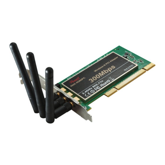
- Page 1 Wireless N PCI Adapter RNX-N360PC User Manual 1910020413...
-
Page 2: Fcc Statement
FCC STATEMENT This equipment has been tested and found to comply with the limits for a Class B digital device, pursuant to part 15 of the FCC Rules. These limits are designed to pro-vide reasonable protection against harmful interference in a residential installation. This equipment generates, uses and can radiate radio frequency energy and, if not in-stalled and used in accordance with the instructions, may cause harmful interference to radio communications. - Page 3 National Restrictions 2400.0-2483.5 MHz Country Restriction Reason/remark Bulgaria General authorization required for outdoor use and public service France Outdoor use limited to 10 Military Radiolocation use. Refarming of the mW EIRP. within the band 2.4 GHz band has been ongoing in recent 2454-2483.5 MHz years to allow current relaxed regulation.
-
Page 4: Table Of Contents
Table of Content Package Contents..................1 Chapter 1 Overview ..................2 Overview of the product ..............2 Features...................2 LED Status ..................3 Chapter 2 Installation Guide ................4 Hardware Installation ...............4 Software Installation.................4 2.2.1 Overview ....................4 2.2.2 Software Installation for Windows XP........... 4 2.2.3 Software Installation for Windows Vista..........9 2.2.4 Software Installation for Windows 7............ -
Page 5: Package Contents
Make sure that the package contains the above items. If any of the listed items are damaged or missing, please contact with your distributor. Conventions: The ‘Adapter’ mentioned in this user guide stands for RNX-N360PC Wireless N PCI Adapter without any explanations. -
Page 6: Chapter 1 Overview
Wireless N Client Utility helps you create a wireless connection immediately. With unmatched wireless performance, reception, and security protection, the RNX-N360PC is the best choice for easily adding or upgrading wireless connectivity to your notebook computer. Features Complies with IEEE802.11n, IEEE802.11g, IEEE802.11b standards... -
Page 7: Led Status
Provides 32-bit PCI interface Supports Ad-Hoc and Infrastructure modes Good capability on anti-jamming Supports roaming between access points when configured in Infrastructure mode Ease to configure and provides monitoring information Supports Windows 2000/ XP/ Vista/ 7 Three External antennas which are listed in a format of 3x3 for three receivers and three transmitters. -
Page 8: Chapter 2 Installation Guide
2.2.2 Software Installation for Windows XP Insert the Resource CD into your CD-ROM drive, and open the folder named RNX-N360PC. Double-click Setup.exe in the proper folder to start the installation, and then the following screen for preparing setup will appear. - Page 9 Figure 2-1 Soon, Figure 2-2 will display after a moment. Click Next to continue. Figure 2-2 After that, you should choose a Setup type. It is recommended that you select Install Client Utilities and Driver. Select Install Driver Only to install driver only (shown in Figure 2-3).
- Page 10 Figure 2-3 Click Browse to change the destination location for the software, then click Next in the screen below (shown in Figure 2-4). Figure 2-4 After that, select the program folder, you should create a new folder name or select one from the Existing Folders list.
- Page 11 Figure 2-5 Choose configuration tool, if you are not sure, please leave it default. Then click Next to continue. Figure 2-6 Wait a while for the setup as shown in Figure 2-7.
- Page 12 Figure 2-7 Note: For Windows XP, the Setup Wizard will notify you of how to proceed with the installation duringthese steps (shown inFigure 2-8). Our drivers have been tested thoroughly, and are able to work with the operating system. Click Continue Anyway to continue the Installation.
-
Page 13: Software Installation For Windows Vista
After all the steps above, you will see the screen below, click Finish to complete the installation. Figure 2-10 2.2.3 Software Installation for Windows Vista Insert the Resource CD into your CD-ROM drive, and open the folder named RNX-N360PC. Double-click Setup.exe in the proper folder to start the installation,... - Page 14 then the following screen for preparing setup will appear. Figure 2-11 Soon, Figure 2-12 will display after a moment. Click Next to continue. Figure 2-12 Click Yes to continue.
- Page 15 Figure 2-13 The following page will display and please wait a moment. Figure 2-14 Note: For Windows Vista, the Setup Wizard will notify you of how to proceed with the installation during these steps (shown in Figure 2-15). Our drivers have been tested thoroughly, and are able to work with the operating system.
-
Page 16: Software Installation For Windows 7
Figure 2-16 2.2.4 Software Installation for Windows 7 Insert the Resource CD into your CD-ROM drive. To continue, find the CD/DVD drive where the installation CD was placed. Open RNX-N360PC folder, and double-click Setup.exe. Then you will see Figure 2-17. - Page 17 Figure 2-17 Soon, Figure 2-18 will display after a moment. Click Next to continue. Figure 2-18 Wait a while for the setup as shown in Figure 2-19.
- Page 18 Figure 2-19 Note: For Windows 7, the Setup Wizard will notify you about the Windows Security with the installation during these steps (shown in Figure 2-20). Our drivers have been tested thoroughly, and are able to work with the operating system. Click Install this driver software anyway to continue the installation.
- Page 19 Figure 2-21...
-
Page 20: Chapter 3 Configuration Guide
Double-click the icon and the Wireless N Client Utility will run. You can also run the utility by clicking the Start → All programs → rosewill → Wireless N Client Utility → Wireless Client Utility. The Wireless N Client Utility provides some integrated and easy... -
Page 21: Profile Management
Figure 3-1 The following table describes the items found on the Current Status screen. Profile Name - This shows the name of current selected configuration profile. The configuration of Profile name will be described on the General tab of Profile Management. -
Page 22: Add Or Modify A Configuration Profile
Add a new profile Modify a Profile Remove a Profile Activate a Profile Import a Profile Export a Profile Scan Available Networks Order profiles Figure 3-2 3.2.1 Add or Modify a Configuration Profile To add a new configuration profile, click New on the Profile Management tab. To modify a configuration profile, select the configuration profile from the Profile list and click Modify. - Page 23 Figure 3-3 Edit the Security tab Select the Security tab in the screen above, and then you can edit the fields to configure the profile. To define the security mode, select the radio button of the desired security mode as follows. Figure 3-4 WPA/WPA2: Wi-Fi Protected Access WPA/WPA2 Passphrase: Wi-Fi Protected Access Passphrase...
- Page 24 both the access point and the station. To define shared encryption keys, choose the Shared Key radio button and click Configure to fill in the Define Shared Keys window (shown in Figure 3-5). Note: The WEP security mode is not available for 802.11n. None: No security (not recommended).
- Page 25 RNX-N360PC wireless adapters. Note: An Infrastructure network contains an Access Point or wireless router. All the wireless devices or clients will connect to the wireless router or access point.
-
Page 26: Remove A Profile
Adapter uses. The channels available depend on the regulatory domain. If the adapter finds no other ad hoc adapters, the channel that the adapter starts the ad hoc network with will be selected automatically. The Adapter must match the wireless mode and channel of the clients it associates. -
Page 27: Export A Profile
3.2.4 Export a profile 1. From the Profile Management screen (shown in Figure 3-2), highlight the profile to export. 2. Click Export…, the Export Profile window will then appear below. 3. Browse the directory to export the profile to. 4. Click Save. The profile should then be exported to the specified location. Figure 3-8 3.2.5 Import a Profile... -
Page 28: Scan Available Networks
Figure 3-9 3.2.6 Scan Available Networks Click Scan on the Profile Management screen (shown in Figure 3-2), the Available Infrastructure and Ad Hoc Networks window will appear below. Click Refresh to refresh the list at any time. Highlight a network name and click Activate to connect to an available network. If no configuration profile exists for that network, the Profile Management window will open the General tab screen. -
Page 29: Diagnostics
Figure 3-11 Highlight the profiles to add to auto profile selection, and click Add. The profile will appear in the Auto Selected Profiles box. Highlight a profile in the Auto Selected Profiles box. Click Move Up or Move Down as appropriate. Note: The first profile in the Auto Selected Profiles box has highest priority, while the last profile has the lowest priority. -
Page 30: Check Driver Information
Broadcast frames transmitted and received Unicast frames transmitted and received Total bytes transmitted and received Figure 3-12 3.3.1 Check Driver Information Click the Adapter Information button in the screen above, you will see the adapter information, including general information about the wireless network adapter and the Network Driver Interface Specification (NDIS) driver. -
Page 31: Configuration For Windows Vista
Figure 3-13 Configuration for Windows Vista After the Adapter's driver has been installed, Windows Vista will display a wireless Network Connection message like this one. Figure 3-14 To establish a connection, please follow the steps below. Right-click the icon in your system tray, then click Connect to a network. Figure 3-15 The following screen will show you available wireless networks. - Page 32 Figure 3-16 To continue, click Connect Anyway. Click the Cancel button to end the connection. Figure 3-17 If the connection is successfully established, the following screen will appear, click Close to finish the connection.
-
Page 33: Configuration For Windows 7
Figure 3-18 Configuration for Windows 7 Wireless N Client Utility is not available for Windows 7. So after the Adapter's driver has been installed, we have to use Windows WLAN Autoconfig to establish a connection. Please follow the steps below. - Page 34 Select the SSID of your Access Point, take rosewill for example. Click Connect. Figure 3-19 If your wireless network is secured, you will be required to enter the security key as shown in Figure 3-20.
- Page 35 If the key entered is correct, you will successfully connect to the network as shown in Figure 3-21. Figure 3-21...
-
Page 36: Chapter 4 Wps Configuration
First, the WPS software should be installed. Insert the Resource CD into your CD-ROM drive, and open the folder named RNX-N360PC. Double-click WPS.exe in the proper folder to start the installation, then the following screen for preparing setup will appear. - Page 37 the button on my access point in the next screen shown in Figure 4-4 and click Next. Figure 4-3 Figure 4-4 3. Then wait a minute until Figure 4-5 appears. Click Finish to complete the WPS configuration.
-
Page 38: Pin Method
Figure 4-5 PIN method There are two ways to configure the WPS by PIN method: Enter a PIN into your AP device. Enter the PIN from your AP device. Following are the detailed configuration procedure of each way. 4.2.1 Enter a PIN into your AP device 1. - Page 39 Figure 4-6 2. Open the Router’s Web-based Utility and click WPS link on the left of the main menu. Then Figure 4-7 will appear. Figure 4-7 3. Click Add device, then you can see Figure 4-8. Select Enter the new device’s PIN and enter the PIN value of the adapter shown in Figure 4-6, click Connect.
-
Page 40: Enter The Pin From Your Ap Device
4.2.2 Enter the PIN from your AP device 1. Open the WPS Utility and you will see Figure 4-3. Click Next to continue. Then Figure 4-4 will appear. Select the third option and enter the PIN value which is labeled on the bottom of the Router. -
Page 41: Appendix A: Specifications
Appendix A: Specifications Normal Interface 32 bit PCI Interface Standards IEEE802.11n; IEEE802.11g; IEEE802.11b; Operating System Windows 2000/Windows XP/Windows Vista/Windows 7 Up to 300Mbps 13.5/27/40.5/54/81/108/121.5/135Mbps 13/26/39/52/78/104/117/130Mbps Radio Data Rate 6.5/13/19.5/26/39/52/58.5/65Mbps 1/2/5.5/11Mbps (Auto Rate Sensing) 11b:CCK,QPSK,BPSK; Modulation 11g:OFDM; 11n: QPSK,BPSK,16-QAM,64-QAM; Media Access Protocol CSMA/CA with ACK Data Security WPA/WPA2;... -
Page 42: Appendix B: Glossary
Appendix B: Glossary 802.11b - The 802.11b standard specifies a wireless product networking at 11 Mbps using direct-sequence spread-spectrum (DSSS) technology and operating in the unlicensed radio spectrum at 2.4GHz, and WEP encryption for security. 802.11b networks are also referred to as Wi-Fi networks. 802.11g - specification for wireless networking at 54 Mbps using direct-sequence spread-spectrum (DSSS) technology, using OFDM modulation and operating in the unlicensed radio spectrum at 2.4GHz, and backward compatibility with IEEE 802.11b... - Page 43 SSID - A Service Set Identification is a thirty-two character (maximum) alphanumeric key identifying a wireless local area network. For the wireless devices in a network to communicate with each other, all devices must be configured with the same SSID. This is typically the configuration parameter for a wireless PC card.
-
Page 44: Appendix C: Faq
Appendix C: FAQ This chapter provides solutions to problems that may occur during the installation and operation of the Wireless Adapter. Read the descriptions below to solve your problems. I cannot communicate with the other computers linked via Ethernet in the Infrastructure configuration. - Page 45 2. There could be too much people using the same radio channel. Ask the owner of the access point to change the channel number. Thank you for purchasing a quality Rosewill Product. Please register your product at: www.rosewill.com for complete warranty information and future support for your product.
Need help?
Do you have a question about the RNX-N360PC and is the answer not in the manual?
Questions and answers