
Related Manuals for Jet EQUIPMENT & TOOLS JWBS-18


Summary of Contents for Jet EQUIPMENT & TOOLS JWBS-18
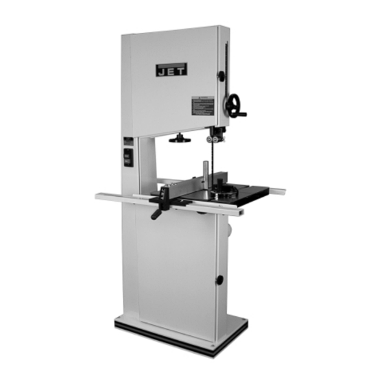
- Page 1 OWNER'S MANUAL JWBS-18 Woodworking Bandsaw JET EQUIPMENT & TOOLS, INC. P.O. BOX 1349 Phone: 253-351-6000 A WMH Company Auburn, WA 98071-1349 Fax: 1-800-274-6840 www.jettools.com e-mail jet@jettools.com M-708750B 12/01...
-
Page 2: Warranty
This manual has been prepared for the owner and operators of a JET JWBS-18 Woodworking Bandsaw. Its purpose, aside from machine operation, is to promote safety through the use of accepted correct operating and maintenance procedures. Completely read the safety and maintenance instructions before operating or servicing the machine. -
Page 3: Warnings
WARNING 1. Read and understand the entire instruction manual before attempting assembly or operation. 2. This bandsaw is designed and intended for use by properly trained and experienced personnel only. If you are not familiar with the proper and safe operation of a bandsaw, do not use until proper training and knowledge have been obtained. -
Page 4: Grounding Instructions
Grounding Instructions Caution: This tool must be grounded while in use to protect the operator from electric shock. In the event of a malfunction or breakdown, grounding provides a path of least resistance for electric current to reduce the risk of electric shock. This tool is equipped with an electric cord having an equipment-grounding conductor and a grounding plug. -
Page 5: 230 Volt Operation
230 Volt Operation If 230V, single phase operation is desired, the following instructions must be followed: 1. Disconnect the machine from the power source. 2. This bandsaw is supplied with four motor leads that are connected for 115V operation, as shown in Figure A. -
Page 6: Table Of Contents
Maintenance............................16 Troubleshooting............................. 17 Part’s Breakdowns and Part’s List ..................... 18-26 Wiring Diagram ............................. 27 Specifications: JWBS-18 Stock Number..........................708750B Cutting Capacity (height) ........................10-1/4” Cutting Capacity (width)........................18-3/8” Maximum Rip Left of Blade w/Fence ....................16-1/2” Maximum Rip Right of Blade w/Fence ....................7-5/8”... -
Page 7: Contents Of Shipping Container
Contents of Shipping Container 1. Bandsaw 1. Table 1. Fence and Rail Assembly 1. Resaw Guide and Knob 1. Miter Gauge 1. Owner’s Manual 1. Warranty Card 1. Accessory Package Contains: Hardware Bag 2. Knobs 1. Hex Wrench 1. Handle 1. -
Page 8: Upper Bearing Guide Adjustment
(D, Fig. 1) indicates the approximate tension according to the width of the blade. The JWBS-18 comes with a 3/4” blade so the tension should be set at 3/4”. Note: It is easier to adjust the bearing guides before mounting the table. -
Page 9: Lower Bearing Guide Adjustment
Lower Bearing Guide Adjustment WARNING Disconnect machine from the power source, unplug before making any adjustments! Blade teeth are sharp! Use care when working near the saw blade. Failure to comply may cause serious injury! 1. Blade tension must be properly adjusted prior to bearing guide setup, see “Adjusting Blade Tension”... -
Page 10: Adjusting 90 Degree Table Stop
Adjusting 90 Degree Table Stop 1. Blade tension must be properly adjusted prior to adjusting 90 degree stop, see “Adjusting Blade Tension” page 14. 2. Loosen lock knobs (A, Fig. 7) and tilt table until it rests against table stop bolt (B, Fig. 7). -
Page 11: Fence Assembly And Adjustment
Fence Assembly and Adjustment 1. Attach the fence (A, Fig. 10) to the fence body (B, Fig. 10) with four 5/16” x 3/4” hex cap bolts, four 5/16” lock washers, and four 5/16” flat washers. 2. Thread a hex nut (D, Fig. 11) onto the pad’s threaded stud (E, Fig. -
Page 12: Resaw Guide
Resaw Guide For resawing attach the post (A, Fig. 13) to fence with the lock knob (B, Fig. 13). There is a slotted hole in the fence that will accommodate the resaw kit. Position the post so that it is centered with the front edge of the blade. -
Page 13: Changing Blades
Changing Blades WARNING Disconnect machine from the power source, unplug! Blade teeth are sharp! Use care when handling the saw blade. Failure to comply may cause serious injury! 1. Disconnect the machine from the power source. 2. Remove the table insert (A, Fig. 16), and table pin (B, Fig. -
Page 14: Adjusting Blade Tension
(B, Fig. 18) indicates the approximate tension according to the width of the blade. The JWBS-18 comes with a 3/4” blade so the tension should be set at 3/4” when using this blade. As you become familiar with the saw, you may find it necessary to change the blade tension from the initial setting. -
Page 15: Replacing Belt
Replacing V-Belt 1. Disconnect the machine from the power source. 2. Release blade tension by turning blade tension hand wheel clockwise. 3. Release belt tension by loosening the two hex cap bolts (A, Fig. 19 the pivot bolt is not shown in the photo). -
Page 16: Electrical Connections
Failure to comply may result in loss of property and/or serious injury! JWBS-18 is rated at 1-1/2 HP, 1Ph, 115V/230V, prewired 115V. The bandsaw comes with a 115V plug (A, Fig. 22). If you switch to 230V a plug needs to be purchased for the bandsaw that matches the 230V outlet you intend to use. -
Page 17: Troubleshooting
Troubleshooting Trouble Possible Cause Solution 1. Saw unplugged 1. Check plug connections 2. Fuse blown or circuit breaker 2. Replace fuse or reset circuit Saw stops or will not start tripped breaker 3. Cord damaged 3. Replace cord 1. Stop not adjusted correctly 1. -
Page 18: Part's Breakdowns And Part's List
Upper Wheel Assembly... - Page 19 Upper Wheel Assembly Index Part Description Size Qty. 1..JWBS18-101W ....White Saw Body................1 2..TS-0152011 ..... Carriage Bolt ..........5/16-18 x 1” ....6 3..JWBS18-103....Upper Wheel Bracket ............... 2 4..TS-0680031 ..... Flat Washer........... 5/16 ......6 5..TS-0720081 ..... Lock Washer ..........5/16 ......6 6..TS-0561021 .....
- Page 20 Lower Wheel and Motor Assembly...
- Page 21 Lower Wheel and Motor Assembly Index Part Description Size Qty. 1..JWBS18-201N ....Bearing Base..................1 2..JWBS20-62...... Adjusting Bolt ................... 4 3..TS-0720091 ..... Lock Washer ..........3/8 ......4 4..TS-0060081 ..... Hex Cap Bolt ..........3/8 x 1-3/4 ....4 5..BB-6204ZZ ......
- Page 22 Blade Guides Assembly...
- Page 23 Blade Guides Assembly Index Part Description Size Qty. 1..TS-0051051 ..... Hex Cap Bolt ..........5/16-18 x 1 ....4 2..TS-0720081 ..... Lock Washer ..........5/16 ......4 3..TS-0680031 ..... Flat Washer........... 5/16 ......8 4..JWBS18-304....Guide Bar Bracket ................1 5..JWBS18-305....
- Page 24 Index Part Description Size Qty. 54 ..JWBS20-354....Bearing Support ................2 55 ..JWBS20-355....Lock Bushing..................1 56 ..JWBS20-357....Hex Socket Cap Screw........3/16 x 3/8 ....2 57 ..JWBS20-358....Bearing Bracket................1...
- Page 25 Table and Fence Assembly...
- Page 26 Table and Fence Assembly Index Part Description Size Qty. 1..JWBS18-401....Lock Knob ..................1 2..TS-0680021 ..... Flat Washer........... 1/4 ......11 3..JWBS18-403....Miter Gauge Body ................1 4..200156......Guide Disc..................1 5..JWBS18-405....Pan Head Screw..........M6 x 8 ......1 6..JWBS18-406....
-
Page 27: Wiring Diagram
Wiring Diagram...
Need help?
Do you have a question about the JWBS-18 and is the answer not in the manual?
Questions and answers