Table of Contents
Advertisement
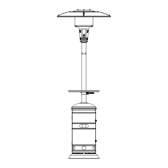
Patio Heater User Manual
Igniter
push
PILOT
LOW
HIGH
OFF
Before returning to your retailer, call our customer service department at
1-888-376-9601.
DANGER:
If you smell gas:
1. Shut off gas to the appliance.
2. Extinguish any open flame.
3. If odor continues, keep away from the
appliance and immediately call your
gas supplier or fire department.
WARNING:
Do not store or use gasoline or other
flammable vapors and liquids in the
vicinity of this or any other appliance.
An LP-cylinder not connected for use
shall not be stored in the vicinity of this
or any other appliance.
WARNING:
Improper installation, adjustment, alteration,
service or maintenance can cause property
damage, injury or death. Read the installation,
operating
and
maintenance
thoroughly before installing or servicing this
equipment.
WARNING:
For outdoor use only.
MODEL#PG139HC
instructions
Advertisement
Table of Contents

Summary of Contents for Red Stone PG139HC
- Page 1 Patio Heater User Manual MODEL#PG139HC DANGER: If you smell gas: 1. Shut off gas to the appliance. 2. Extinguish any open flame. 3. If odor continues, keep away from the appliance and immediately call your gas supplier or fire department.
-
Page 2: Table Of Contents
TABLE OF CONCENTS Product Specifications…………………………………………………………...2 Safety Information………………………………………………………………..3-5 Package Contents………………………………………………………………..6 Hardware Contents………………………………………………………….…...7 Preparation…………………………………………………………………..7 Assembly Instructions………………………………………………………..7-14 Installing an LP Gas Tank………… ……………………………………….….. .14-15 Safety Check………………………………………………………………….… .15 Lighting Instructions………………………………………………………….…..16 Care and Maintenance ………………………………………………………….17 Troubleshooting…………………………………………………………………..18 Warranty…………………………………………………………………………..18 PRODUCT SPECIFICATIONS Product Specifications Certification Height Overall 86.60 inches Reflector Diameter 31.50 inches Rated Heat Input... -
Page 3: Safety Information
SAFETY INFORMATION Please read and understand this entire manual before attempting to assemble, operate or install the product. If you have any questions regarding the product, please call customer service at: 1-888-376-9601 from 8:00 am to 5:00 pm Eastern time , Monday to Friday. - Page 4 SAFETY INFORMATION Keep the appliance area clear and free from combustible materials, gasoline and other flammable vapors and liquids. Do not obstruct the flow of combustion and ventilation air. Keep the ventilation opening(s) of the cylinder enclosure free and clear from debris.
- Page 5 control compartment, burners and circulating air passageways of the heater be kept clean. . Every part of the heater shall be secure against displacement and shall be constructed to maintain a fixed relationship between essential parts under normal and reasonable conditions of handling and usage. Parts not permanently secured shall be designed so they cannot be incorrectly assembled and cannot be improperly located or misaligned in removing or replacing during cleaning or other servicing.
-
Page 6: Package Contents
PACKAGE CONTENTS Part Description Quantity Part Description Quantity Top Dome Cylinder Restraint Chain KD Dome Front Shrould (Cylinder door) Burner Assembly Base Post Caster Platform Latch Cylinder Cover Control Knob Tabletop Upper Post Assembly (Pre-assembled) Tabletop Support Heat Insulation Plate Assembly Back Shroud Cylinder Strip... -
Page 7: Hardware Contents
HARDWARE CONTENTS M8X15mm Bolt 8.5 mm Washer M8 Nut M5X10 mm Bolt ST4.2X10mm screw M5 X 8mm Bolt X 12 M5 Acorn Nut X 15 5 mm Washer X 15 PREPARATION Before beginning assembly of product, make sure all parts are present. Compare parts with package contents list and diagram above. -
Page 8: Assembly Instructions
ASSEMBLY INSTRUCTIONS Fig. 1 1. Take the product out of package, disassemble Cylinder Cover (F) by loosening three M6 Bolts. (Fig. 1) Bolt Fig. 2 2. Attach Post (D) to Platform (E) with three Bolts (AA), three Washers (BB) and three Nuts (CC) (Fig. - Page 9 Fig. 3 3. Connect Cylinder Cover (F) to assembled Back Shroud (I) by using three Bolts (Fig. 3), M6X10. and place the Ring (T) on the Post (D) Bolt Bolt M6X10 Fig. 4 4. Fix Tabletop Support (H) to Tabletop (G) by using four screws (EE).
- Page 10 Fig. 5 5. Disassemble the M5 x 10 mm Bolt from the Post (D). Put the assembled tabletop (G)+(H) to Post (D). Don’t reassemble M5 X 10 the M5 x 10 mm Bolt to the Post (D) until mm Bolt Step 6 is complete.
- Page 11 Fig. 7 7. Assemble the four KD Domes (B) with four M5 × 6 mm Bolts (FF.), four M5 Acorn Nuts (GG.) and four 5 mm Washers (HH). Attach Top Dome (A) to assembled KD Domes by using eight M5 × 8 mm Bolts (FF.), eight M5 Acorn Nuts (GG.) and eight 5 mm Washers (HH) (Fig.
- Page 12 Fig. 9 9. Insert the cylinder strip (S) into the holes of bracket on the shroud sides, making the strip parallel to the Base, in order to prevent storing the gas cylinder more than 20 lb. Fig. 10 10. Put the gas cylinder into the shroud. Keep the cylinder vertically upright on the base for vapor withdraws.
- Page 13 Fig. 11 11. Connect Regulator & Hose Assembly (J) to cylinder (not included). (Fig. 11) Note: Check for leaks after connecting the gas cylinder prior to each use according to the “Checking for Leaks” section on page 14. Fig. 12 12.
-
Page 14: Installing An Lp Gas Tank
Fig. 13 13. If the heater is installed on a surface with a gradient more than 15°, fix the base to the surface by using two ground screws through the two holes on base as indicated. (Fig. 13) Installing LP Gas Tank Installing LP Gas Tank 1. -
Page 15: Safety Check
3. Disconnect 20 lb. LP Gas Tank Before disconnecting make sure the LP gas tank valve is “OFF”. Disconnect gas line to tank by turning knob counterclockwise until it is loose. Store the LP gas tank in a proper location SAFETY CHECK Fig.14 Checking for Leaks... -
Page 16: Lighting Instructions
Fig.15 Lighting Instruction Turn the LP gas tank valve OFF. Push control knob in, turn OFF, and wait 5 minutes for any gas to clear. Igniter 2. Turn the tank valve ON. Push control knob in and rotate to push PILOT. -
Page 17: Care And Maintenance
CARE AND MAINTENANCE To obtain the best performance from your heater make sure you perform the following maintenance activities on a regular basis: a. Keep exterior surfaces clean, use warm soapy water for cleaning. Never use flammable or corrosive cleaning agents. Keep the area around the burner and control assembly dry at all times. -
Page 18: Troubleshooting
TROUBLESHOOTING Problem Possible Cause Corrective Action Burner won’t light Gas pressure is low. Turn tank valve “OFF” and replace the tank The orifice is blocked. Clear blockage. Control knob is not in “ON” position. Turn control knob to “ON” Burner flame is low Gas pressure is low. Turn tank valve “OFF”...
Need help?
Do you have a question about the PG139HC and is the answer not in the manual?
Questions and answers