Cisco Catalyst 2950 Getting Started Manual
Hide thumbs
Also See for Catalyst 2950:
- Configuration manual (710 pages) ,
- Command reference manual (686 pages) ,
- Software configuration manual (674 pages)
Table of Contents
Advertisement
Catalyst 2950 Switch Getting Started Guide
INCLUDING LICENSE AND WARRANTY
1
About this Guide
2
Taking Out What You Need
3
Running Express Setup
4
Managing the Switch
5
Rack-Mounting
6
Connecting to DC Power
7
In Case of Difficulty
8
Obtaining Documentation
9
Obtaining Technical Assistance
10
Cisco Limited Lifetime Hardware Warranty Terms
Getting Started Guide
Advertisement
Table of Contents

Related Manuals for Cisco Catalyst 2950


Summary of Contents for Cisco Catalyst 2950
- Page 1 Getting Started Guide Catalyst 2950 Switch Getting Started Guide INCLUDING LICENSE AND WARRANTY About this Guide Taking Out What You Need Running Express Setup Managing the Switch Rack-Mounting Connecting to DC Power In Case of Difficulty Obtaining Documentation Obtaining Technical Assistance...
-
Page 2: About This Guide
When using the online publications, refer to the documents that match the Cisco IOS software version running on the switch. The software version is on the Cisco IOS label on the switch rear panel. You can order printed copies of the manuals from the Cisco.com sites and from the telephone numbers listed in the “Obtaining Documentation”... -
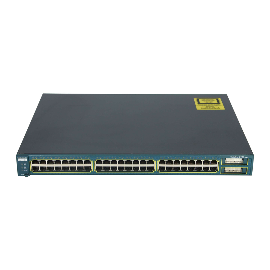
Page 3: Shipping Box Contents
STA T UTI L DUP LX SPE ED MO DE Ca tal ys t 29 SER IES Catalyst 2950 switch Two 19-inch mounting brackets Four number-12 Phillips machine screws Four number-8 Phillips truss-head screws Console cable Six number-8 Phillips flat-head screws... -
Page 4: Running Express Setup
Running Express Setup When you first set up the switch, you should use Express Setup to enter the initial IP information. This enables the switch to connect to local routers and the Internet. You can then access the switch through the IP address for further configuration. - Page 5 Connect a straight-through Step 7 Category 5 Ethernet cable (not provided) to any 10/100 or SYST STAT UTIL DUPL X SPEE D 10/100/1000 Ethernet port on the MODE Cat aly st 295 SERIE S switch front panel and to the Ethernet port on the PC.
- Page 6 Enter this information in the Network Settings fields: Step 12 • In the Management Interface (VLAN ID) field, the default is 1. Enter a new VLAN ID only if you want to change the management interface through which you manage the switch and to which you assign IP information.
-
Page 7: Refreshing The Pc Ip Address
2. Enter the switch IP address in the web browser, and press Enter. The device manager page appears. 3. Use the device manager to perform basic switch configuration and monitoring. Refer to the device manager online help for more information. 4. For more advanced configuration, download and run the Cisco Network Assistant described in the next section. -
Page 8: Downloading Cisco Network Assistant
Downloading Cisco Network Assistant Cisco Network Assistant is a free software program that you download from Cisco.com and run on your PC. Network Assistant offers advanced options for configuring and monitoring multiple devices, including switches, switch clusters, switch stacks, routers, and access points. -
Page 9: Rack Mounting
This section covers basic 19-inch rack-mounting and switch port connections. As an example, all the illustrations show the Catalyst 2950G-48-EI switch. You can install and connect other Catalyst 2950 switches as shown in these illustrations. For alternate mounting procedures, such as installing the switch in a 24-inch rack or on a wall, and for additional cabling information, refer to the Catalyst 2950 Switch Hardware Installation Guide on Cisco.com. -
Page 10: Installation Warning Statements
Installation Warning Statements This section includes the basic installation warning statements. Warning Installation of the equipment must comply with local and national electrical codes. Statement 1074 Warning Only trained and qualified personnel should be allowed to install, replace, or service this equipment. - Page 11 Warning If a redundant power system (RPS) is not connected to the switch, install an RPS connector cover on the back of the switch. Statement 265 Warning Class 1 laser product. Statement 1008 Warning Statements for Connecting to DC Power These statements apply when connecting a Catalyst 2950G-24-EI-DC or Catalyst 2950ST-24 LRE 997 switch to DC power.
-
Page 12: Attaching The Brackets
Attaching the Brackets Use six Phillips flat-head screws to attach the long side of the brackets to Catalyst 2950G-48-EI, 2950SX-48-SI, or 2950T-48-SI switches in one of three mounting positions. Use four Phillips flat-head screws to attach the long side of the brackets for all switches other than the Catalyst 2950G-48-EI, 2950SX-48-SI, or 2950T-48-SI models. -
Page 13: Rack-Mount The Switch
Rack-Mount the Switch Use the black Phillips machine screw to attach the cable guide to the left or right bracket. Use the four number-12 Phillips machine screws to attach the brackets to the rack. Cable guide SYS T STA T UTI L DU PLX SPE ED... -
Page 14: Connect To The Switch Ports
Connect to the Switch Ports This section describes how to connect to the fixed switch ports and to the SFP and GBIC module ports. Connect to 10/100 and 10/100/1000 Ports Follow these steps: When you connect to servers, Step 1 workstations, IP phones, wireless access points, and routers, insert a SY ST... - Page 15 SFP module port GBIC module port For a list of supported modules, refer to the release notes on Cisco.com. For detailed instructions on installing and removing modules, refer to the documentation that came with the SFP or GBIC module. Removing and installing an SFP module can shorten its useful life. Do not remove and Caution insert SFP modules more often than is absolutely necessary.
-
Page 16: Connecting To Dc Power
Connecting to DC Power To connect the Catalyst 2950G-24-EI-DC or Catalyst 2950ST-24 LRE 997 switch to a DC-input power source, follow the steps in this section. Equipment That You Supply You need to supply these tools and equipment: • Ratcheting Phillips-head torque screwdriver •... -
Page 17: Wiring The Dc Input Power Source
Slide the exposed area of the 6-gauge wire Step 3 into the ground lug, and use the crimping tool to crimp the lug to the wire. Step 4 Using the ratcheting screwdriver, torque the ground lug screws to 15 lbf-in. (240 ounce-force inches [ozf-in.]) to attach the ground lug to the switch. - Page 18 Using the ratcheting torque screwdriver, Step 4 torque each terminal block captive screw (above the installed wire leads) to 4.5 lbf-in. (72 ozf-in.). Return Feed A Negative Return Feed B Negative Insert the terminal block plug in the terminal Step 5 block header on the rear panel of the Catalyst 2950G-24-EI-DC switch or on the 3 6 - 7 2 V...
-
Page 19: In Case Of Difficulty
In Case of Difficulty If you experience difficulty, help is available here and on Cisco.com. This section includes Express Setup troubleshooting, how to reset the switch, how to access help online, and where to find more information. Troubleshooting Express Setup If Express Setup does not run, or if the Express Setup page does not appear in your browser: •... -
Page 20: Resetting The Switch
Express Setup as described in the “Running Express Setup” section on page 4. Accessing Help Online First look for a solution to your problem in the troubleshooting section of the Catalyst 2950 Hardware Installation Guide or the Catalyst 2950 and Catalyst 2955 Software Configuration Guide on Cisco.com. -
Page 21: Obtaining Documentation
• Catalyst 2950 Switch Hardware Installation Guide (order number DOC-7811157=). This guide provides complete hardware descriptions and detailed installation procedures. • Regulatory Compliance and Safety Information for the Catalyst 2950 Switch (order number DOC-7816625). This guide contains agency approvals, compliance information, and translated warning statements. -
Page 22: Ordering Documentation
You can find instructions for ordering documentation at this URL: http://www.cisco.com/univercd/cc/td/doc/es_inpck/pdi.htm You can order Cisco documentation in these ways: • Registered Cisco.com users (Cisco direct customers) can order Cisco product documentation from the Ordering tool: http://www.cisco.com/en/US/partner/ordering/index.shtml • Nonregistered Cisco.com users can order documentation through a local account representative by calling Cisco Systems Corporate Headquarters (California, USA) at 408 526-7208 or, elsewhere in North America, by calling 800 553-NETS (6387). -
Page 23: Obtaining Technical Assistance
URL: http://www.cisco.com/techsupport/servicerequest For S1 or S2 service requests or if you do not have Internet access, contact the Cisco TAC by telephone. (S1 or S2 service requests are those in which your production network is down or severely degraded.) Cisco TAC engineers are assigned immediately to S1 and S2 service requests to help keep your business operations running smoothly. -
Page 24: Definitions Of Service Request Severity
Definitions of Service Request Severity To ensure that all service requests are reported in a standard format, Cisco has established severity definitions. Severity 1 (S1)—Your network is “down,” or there is a critical impact to your business operations. You and Cisco will commit all necessary resources around the clock to resolve the situation. -
Page 25: Cisco Limited Lifetime Hardware Warranty Terms
• iQ Magazine is the quarterly publication from Cisco Systems designed to help growing companies learn how they can use technology to increase revenue, streamline their business, and expand services. The publication identifies the challenges facing these companies and the technologies to help solve them, using real-world case studies and business strategies to help readers make sound technology investment decisions. - Page 26 Duration of Hardware Warranty A Cisco product hardware warranty is supported for as long as the original end user continues to own or use the product, provided that the fan and power supply warranty is limited to five (5) years. In the event of a discontinuance of product manufacture, the Cisco warranty support is limited to five (5) years from the announcement of the discontinuance.
- Page 28 Vietnam • Zimbabwe CCVP, the Cisco logo, and Welcome to the Human Network are trademarks of Cisco Systems, Inc.; Changing the Way We Work, Live, Play, and Learn is a service mark of Cisco Systems, Inc.; and Access Registrar, Aironet, Catalyst, CCDA, CCDP, CCIE, CCIP, CCNA, CCNP, CCSP, Cisco, the Cisco Certified Internetwork Expet logo, Cisco IOS,...
Need help?
Do you have a question about the Catalyst 2950 and is the answer not in the manual?
Questions and answers