Table of Contents
Advertisement
Quick Links
Advertisement
Table of Contents

Related Manuals for dbx 120A


Summary of Contents for dbx 120A
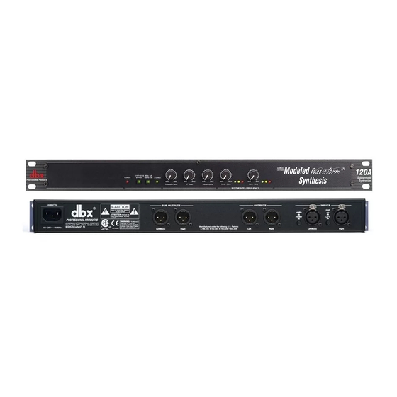
- Page 1 ® 120A Subharmonic Synthesizer with Modeled Waveform Synthesis ™ User Manual...
-
Page 2: Important Safety Instructions
IMPORTANT SAFETY INSTRUCTIONS WARNING FOR YOUR PROTECTION C A U T I O N PLEASE READ THE FOLLOWING: R I S K O F E L E C T R I C S H O C K KEEP THESE INSTRUCTIONS D O N O T O P E N A T T E N T I O N : R I S Q U E D E C H O C E L E C T R I Q U E - N E P A S O U V R I R... - Page 3 Declaration of Conformity. Operation is subject to the following September 25, 2001 two conditions: European Contact: Your local dbx Sales and Service Office • this device may not cause harmful interference, and or Harman Music Group 8760 South Sandy Parkway •...
-
Page 4: Table Of Contents
120A Table of Contents Introduction 0.1 Defining the 120A ..........i 0.2 Service Contact Info.........ii 0.3 Warranty............ii Section 1 - Operation and Appendix 1.1 Rear Panel Connections ........1 1.2 Front Panel Connections........1 1.3 Operating Notes ..........2 1.4 Basic Connection..........4 Appendix A.1 Block Diagram ..........5 A.2 Specifications............6... - Page 5 120A INTRODUCTION INTRO CUSTOMER SERVICE INFO 120A DEFINED WARRANTY INFO ®...
- Page 6 ONLY, along with a separate subwoofer output with its own level control. This manual will be your guide to understanding the full functionality of the powerful 120A. After you have become familiar with the unit, we encourage you to experiment and find cre- ative ways that the 120A can help you optimize your specific application.
-
Page 7: Introduction
In no event shall dbx or its dealers be liable for spe- cial or consequential damages or from any delay in the performance of this warranty due to causes beyond their control. - Page 8 120A ®...
-
Page 9: Rear Panel Connections
1.1 Rear Panel Connections A- IEC Power Cord Receptacle This is the power cord receptacle of the 120A. An IEC cord is included with the shipped product. B- Subwoofer Output Connector This output connector sends signal to your subwoofer amplifier, the low bass signal which ranges from 20 Hz up to the crossover frequency (80Hz to 120Hz). -
Page 10: Operating Notes
K- LF Boost Control This control is used to even out the total apparent Bass output of the 120A. Use the LF Boost to gently boost the bass on each channel (after the harmonics are summed in) to fill in the gap between the synthesized low bass (below 55 Hz) and the mid-bass of the original pro- gram. - Page 11 120A is more portable than a pair of two larger speakers. Turntable Feedback and Low Frequency Rumble If you are using the 120A with a turntable, the increased levels of bass may make your turntable system more susceptible to feedback, wherein the turntable base, platter, cartridge/stylus, and/or the disc itself actually pickup and replay bass from the speakers.
-
Page 12: Basic Connection
120A for guitar or bass; main outs of a submixer as the signal is sent to main mixer. The 120A can be used either before or after an external electronic crossover. When using a chain of processors, the 120A should generally be placed as far down the chain as possible. -
Page 13: Appendix
120A Appendix Block Diagram Appendix A.1 Block diagram ®... -
Page 14: Specifications
12dB/octave high pass (-3dB @ 80 Hz or 120Hz); 6dB/octave derived low pass. Phase-coherent (unity-sum) Power Requirements: 100-120VAC; 50/60Hz DO Version, 220-240VAC; 50/60Hz EU Version Dimensions: 1.75"x19"x6.2" (4.5cm x 48.3cm x 15.75cm) Rack Space: 1 Rack Unit Weight: Net/Shipping: 4.75 lbs/8 lbs, 2.2kg/3.7kg ® ® 120A User Manual... -
Page 15: Wiring Diagrams
The output’s impedance at 100Ω, allowing operation with virtually any load. Nominal operating level is +4dBu into 600Ω. If using 1/4” mono plugs, at the output, the 120A will be grounded to the load device. This can cause a ground loop. By using 1/4” balanced phone plugs, the grounds of both the 120A and the load can be isolat- ed to reduce hum. - Page 16 ® A Harman International Company 8760 South Sandy Pkwy. Sandy, Utah 84070 Phone: (801) 568-7660 Fax: (801) 568-7662 Questions or comments? E•mail us at: customer@dbxpro.com or visit our World Wide Web home page at: www.dbxpro.com 18-2217 ®...
Need help?
Do you have a question about the 120A and is the answer not in the manual?
Questions and answers