Advertisement
Quick Links
400 D / 800 D
M-300 / M-400
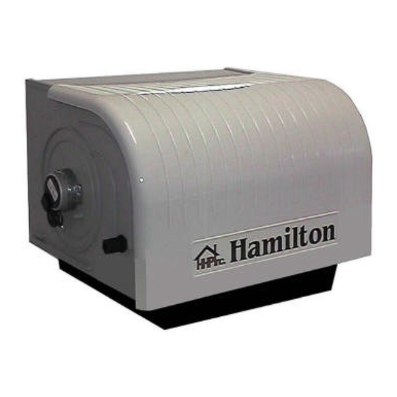
Installation Instructions for Furnace Humidifier
Plastic Models - Standard and Self-cleaning
Please read the instructions carefully before starting the installation.
Version 3 - June 2001
For future use, please copy the free help line number into the space below.
Free help line for technical assistance:
1-800-879-0123
Advertisement

Subscribe to Our Youtube Channel
Summary of Contents for Hamilton 400 D
- Page 1 400 D / 800 D M-300 / M-400 Installation Instructions for Furnace Humidifier Plastic Models - Standard and Self-cleaning Please read the instructions carefully before starting the installation. Version 3 - June 2001 For future use, please copy the free help line number into the space below.
-
Page 2: Warnings And Disclaimer
BEFORE YOU START - GENERAL SAFETY AND INSTALLATION PRECAUTIONS Please read and understand these instructions fully before you begin this installation and save them for future reference. The manufacturer will assume no responsibility and the warranty will be void if the user does not adhere to the following precautions. WARNINGS AND DISCLAIMER Installation Precautions 1) This humidifier will be connected to and used under water pressure and it must be installed in such a way that if a leak... - Page 3 Self-cleaning model: Normally, when the warm air of the furnace flows through the humidifier, it evaporates the water contained in the foam pad, leaving behind mineral deposits. In the self-cleaning humidifier, the principle is to eliminate a small quantity of water containing a high level of minerals before filling the unit with fresh water.
- Page 4 OPTIONAL: If the damper is snugly in place and can remain in a fixed position, screw #4 may be left out. This will allow for easier opening and closing of the air damper. 8. Installing the flexible duct (Please see the general view Fig. 2) Measure the required flexible duct length necessary to connect the humidifier to the air take-off collar (2.3), so it does not sag.
- Page 5 12. Connecting the supply tubing to the humidifier (Please see Fig. 7) Please ensure that operations 12, 13 and 14 are completed in sequence. The plastic tubing MUST be kept away from hot surfaces (e.g. the warm air duct or the exhaust vent). Please measure carefully before cutting.
- Page 6 WARNING: Always check that you are not about to cut or drill into any air conditioning or electrical accessory during installation. Mark and drill the mounting holes and cut an opening for the humidistat. Push the two quick connectors (9.5) on the humidistat (9.3) terminals identified #2 (or COM) and #3 (or NO). Split the wire coming from the transformer (9.1) in two on a suitable distance to connect one end to one of the motor (9.2) wires and the other end to the humidistat terminal identified #2 (or COM).
- Page 7 Spare parts for this flow-thru model are available in kits only. Fig. Description Quantity per kit Flexible duct Motor Kit #5 Motor Metal screw #6 x 1/2” 2 Float & Valve Kit #2 Automatic valve Valve arm Float Plastic hexagonal nut 7/16-24 Pivot point of the float Stainless steel screw 10-32 x 1/2”...
- Page 12 WARNING: This diagram is not drawn to actual demensions. Please use measurements given to obtain actual size.
- Page 13 Hamilton will not be responsible for loss of use of any product: loss of time, inconvenience, or any other indirect, incidental, or consequential damages with respect to person or property, whether caused directly or indirectly by the product, or as a result of breach of contract, neglect or otherwise.


Need help?
Do you have a question about the 400 D and is the answer not in the manual?
Questions and answers