
Related Manuals for Fujitsu Siemens Computers D1321


Summary of Contents for Fujitsu Siemens Computers D1321
- Page 1 S Y S T E M B O A R D D 1 3 2 1 S Y S T E M B O A R D D 1 3 2 1 TECHNICAL MANUAL TECHNICAL MANUAL...
- Page 2 Ihre Verkaufsstelle Weitere Informationen finden Sie im Handbuch "Sicherheit, Garantie und Ergonomie". Aktuelle Informationen zu unseren Produkten, Tipps, Updates usw. finden Sie im Internet: http://www.fujitsu-siemens.com Are there ..any technical problems or other questions you need clarified? Please contact:...
- Page 4 Questo manuale è stato stampato su carta da riciclaggio. Denna handbok är tryckt på recyclingpapper. Dit handboek werd op recycling-papier gedrukt. Herausgegeben von/Published by Fujitsu Siemens Computers GmbH A26361-D1321-Z120-1-7419 Bestell-Nr./Order No.: Printed in the Federal Republic of Germany AG 0801...
- Page 5 Deutsch English Systembaugruppe D1321 System Board D1321 Technisches Handbuch Technical Manual Ausgabe August 2001 August 2001 edition...
- Page 6 Alle weiteren genannten Warenzeichen sind Warenzeichen oder eingetragene Warenzeichen der jeweiligen Inhaber und werden als geschützt anerkannt. Copyright ã Fujitsu Siemens Computers GmbH 2001 Alle Rechte vorbehalten, insbesondere (auch auszugsweise) die der Übersetzung, des Nachdrucks, der Wiedergabe durch Kopieren oder ähnliche Verfahren.
-
Page 7: Table Of Contents
Settings with switches and jumpers ....................7 Recovering System BIOS - switch 2 ..................7 Add-on modules ..........................8 Installing and removing processors....................9 Upgrading main memory......................10 Installing network board with WOL................... 11 Replacing the lithium battery....................12 Glossary ............................13 A26361-D1321-Z120-1-7419... -
Page 9: Introduction
Please observe the safety information provided in the "Important notes" chapter in the device's operating manual. Incorrect replacement of the lithium battery may lead to a risk of explosion. It is therefore essential to observe the instructions in the "Add-on modules" - "Replacing the lithium battery" section. English - 1 A26361-D1321-Z120-1-7419... -
Page 10: Information About Boards
The equipment and tools you use must be free of static charges. Remove the power plug from the mains supply before inserting or removing boards containing ESDs. Always hold boards with ESDs by their edges. Never touch pins or conductors on boards fitted with ESDs. 2 - English A26361-D1321-Z120-1-7419... -
Page 11: Features
Floppy disk write-protection via BIOS Setup Boot hard disk virus warning function Flash BIOS and EEPROMs (on the memory modules) virus protection function. 3 PCI slots PCI slots support 3.3 V main and auxiliary voltages. English - 3 A26361-D1321-Z120-1-7419... -
Page 12: External Ports
9b = Audio Line-In 5 = Serial port 2 9c = Audio Micro-In 6 = LAN connector 7 = USB ports A and B The components and connectors marked are not necessarily present on the system board. 4 - English A26361-D1321-Z120-1-7419... -
Page 13: Internal Ports And Connectors
5 = IDE drives 1 and 2 (primary) 14 = Fan 1 (e.g. for the processor) 6 = Voltage indicator LED 7 = Fan 2 8 = Cover monitoring The components and connectors marked are not necessarily present on the system board. English - 5 A26361-D1321-Z120-1-7419... -
Page 14: Hard Disk Connection
B, C, D, A PCI bus slot 1 C, D, A, B PCI bus slot 2 D, A, B, C PCI bus slot 3 A, B AGP slot First USB controller Second USB controller LAN controller SMBus AC'97 Audio 6 - English A26361-D1321-Z120-1-7419... -
Page 15: Settings With Switches And Jumpers
BIOS you need a Flash BIOS Diskette (please call our customer service centre). The System BIOS executes from floppy drive A: and the inserted "Flash-BIOS- Diskette" restores the System BIOS on the system board. Normal operation (default setting). English - 7 A26361-D1321-Z120-1-7419... -
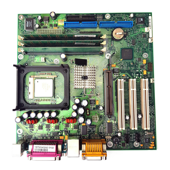
Page 16: Add-On Modules
5 = Lithium battery 2 = Location bank 1 for main memory 6 = PCI slots 1, 2, 3 3 = Location bank 2 for main memory 7 = AGP slot 4 = Location bank 3 for main memory 8 - English A26361-D1321-Z120-1-7419... -
Page 17: Installing And Removing Processors
The angled corner of the processor may be covered by the heat sink. In this case let yourself be guided by the marking in the rows of pins on the underside of the processor. Ê Push the lever back down until it clicks into place (5). English - 9 A26361-D1321-Z120-1-7419... -
Page 18: Upgrading Main Memory
At the same time flip the lateral holders upwards until the memory module snaps in place (2). Removing a memory module Ê Push the clips on the right and left of the compartment outward (1). Ê Carefully remove the memory module from the compartment (2). 10 - English A26361-D1321-Z120-1-7419... -
Page 19: Installing Network Board With Wol
5 V auxiliary voltage of at least 1 A. If the system board was not already incorporated in a device when you bought it you must check whether your power supply can provide the auxiliary voltage. You may find further information in the supplied description of the network board. English - 11 A26361-D1321-Z120-1-7419... -
Page 20: Replacing The Lithium Battery
The following graphic representation is also valid if the lithium battery is built-in vertically. Ê Lift the contact (1) a few millimetres and remove the battery from its socket (2). Ê Insert a new lithium battery of the same type into the socket (3). 12 - English A26361-D1321-Z120-1-7419... -
Page 21: Glossary
Super Video Graphic Adapter Graphics Performance Universal Serial Bus Accelerator Inter Integrated Circuit Video Graphic Adapter IAPC Instantly Available Power Wake On LAN Managed Desktop PC Design I/O Controller Hub Intelligent Drive Electronics IPSEC Internet Protocol Security English - 13 A26361-D1321-Z120-1-7419...