Table of Contents
Advertisement
Quick Links
Advertisement
Table of Contents

Subscribe to Our Youtube Channel
Related Manuals for DW FEARN VT2

Summary of Contents for DW FEARN VT2
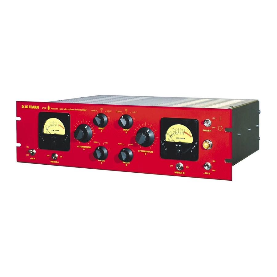
- Page 1 D.W. FEARN VT-1 VT-2 Vacuum Tube Microphone Preamplifiers Operating Instructions...
- Page 2 How to Contact us: Telephone: 610-793-2526 Fax: 610-793-1479 Mail: P.O. Box 57, Pocopson, PA 19366 U.S.A. Shipping Address: 182 Bragg Hill Road West Chester, PA 19382 U.S.A. e-mail: dwfearn@dwfearn.com www.dwfearn.com D.W. FEARN VT-1 & VT-2 Microphone Preamplifers...
-
Page 3: Final Test Report
VT-1 / VT-2 Vacuum Tube Microphone Preamplifier Final Test Report Model _______________ Serial Number_______________Mains Voltage ______________ Date ___________________ Tested by ________ VU Calibrated to _______________ dBm Test Equipment ____________________________ Microphone ________________________ Channel _______ Channel _______ Frequency Response: Frequency Response: 20 cps to 20 kc/s +/- ___________ dB 20 cps to 20 kc/s +/- ___________ dB THD+Noise: THD+Noise:... -
Page 4: Table Of Contents
T a b l e o f C o n t e n t s Final Test Report CE Certification Data Warranty ..................7 History of the VT-1 and VT-2 ............9 1. Specifications ................13 2. Description................15 3. Installation ................17 4. Operation ................21 5. - Page 5 D.W. Fearn shall not be liable for technical or editorial errors or omissions in this manual, nor for incidental or consequential damages resulting from the use of this material. This instruction manual contains information protected by copyright. No part of this manual may be photocopied or reproduced in any form without prior written consent from D.W.
-
Page 6: Warranty
Limited 5-Year Warranty During the warranty period, D.W. Fearn will, at no additional charge, repair or replace defective parts with new parts. This warranty does not extend to any VT-1 or VT-2 that has been damaged or ren- dered defective as a result of accident, misuse, or abuse; by the use of parts not man- ufactured or supplied by D.W. -
Page 7: History Of The Vt-1 And Vt-2
History of the VT-1 and VT-2 Vacuum Tube Microphone Preamplifiers ONE DAY IN 1991 I was going through some old masters in a closet at home and came across a reel from 1968. It was one of the first studio recordings I ever made. I pulled the tape box off the shelf and thought about those days. - Page 8 Could that sound be duplicated today? I dug out my old RCA Receiving Tube Manual and several other old reference books and reviewed the vacuum tube theory I hadn’t thought about for years. A quick check in the supplier’s catalogs confirmed that tubes were still easy to obtain.
- Page 9 from low distortion to extreme distortion (clipping). This is a good trait, since when operat- ed right up to their maximum level solid state amplifiers can maintain excellent performance. Digital audio circuits have similar characteristics. Vacuum tube circuits, on the other hand, show a gradual increase in distortion throughout their operating range.
- Page 10 To avoid this, the VT-1 design eliminates as many of these trouble-prone connections as pos- sible. In fact, the only non-soldered connections from input to output are the input select and phase reverse switches and the tube sockets. The input and phase switches are rotary types with ceramic insulation and massive silver contacts.
-
Page 11: Specifications
S P E C I F I C AT I O N S Input 150 ohms Input Load Impedance 1.5k ohms Minimum Input Level -65 dBm nominal Maximum Input Level @ 20 cps -30 dBm without pad -5 dBm with 20 dB pad Gain 53 dB minimum Frequency... -
Page 12: Description
D E S C R I P T I O N The Model VT-1 and VT-2 Vacuum Tube Microphone Preamplifiers are designed to provide recording professionals with a sonically superior input device. (Unless there is a specific rea- son to address a difference between the VT-1 and VT-2 preamplifiers, the device will be referred to as the “VT-2.”) It is typically used in sound recording studios for recording indi- vidual tracks. -
Page 14: Installation
I N S TA L L AT I O N The VT-2 is carefully packed for shipment and it should survive all but the most brutal han- dling. If there is any damage, keep the shipping material for use during any possible claim for damage with the shipper. - Page 15 P P o o w w e e r r The VT-2 is designed to operate from 100, 120, or 220-240 volt, 50/60 Hz power. The unit will be shipped wired for the voltage specified in the order, but may be changed in the field if necessary.
- Page 16 I I n n p p u u t t a a n n d d O O u u t t p p u u t t C C o o n n n n e e c c t t i i o o n n s s See Figure 1.
- Page 17 D.W. FEARN VT-1 & VT-2 Microphone Preamplifers...
-
Page 18: Operation
O P E R AT I O N I I n n p p u u t t Since the input cable will be carrying very low level audio, it is important that a well-shield- ed cable is used. There should be no additional connectors, patch jacks, switches, etc. between the microphone and the VT-2 input. - Page 19 The VT-2 can feed balanced or unbalanced inputs with no need for any modification in out- put wiring. Either pin 2 or 3 can be grounded, although pin 2 is normally used as the ”hot” and pin 3 grounded in unbalanced configurations. C C O O N N T T R R O O L L S S ( ( s s e e e e F F i i g g u u r r e e 2 2 .
- Page 20 micing situations. In the “0” position, the VT-2 can accept up to about a -30 dBm input sig- nal at 20 cps with full gain (53 dB) without an increase in distortion. I I n n p p u u t t “ “ - - 2 2 0 0 ” ” p p o o s s i i t t i i o o n n . . In the “-20”...
- Page 21 connector (through precision matched resistors), and the negative to pin 1 (ground). The DC voltage is recovered at the microphone with negligible effect on the audio signal. Vacuum tube condenser mics and dynamic microphones do not require this power and the +48 switch (1) should be turned off when using non-phantom powered mics.
- Page 22 the recording/monitoring chain. The effect of reversed absolute polarity is subtle, but signif- icant with some sounds. If the “Reverse” position sounds better, use it. With more than one microphone on the same sound source (or picking up leakage from another sound source), the Phase switch may have a profound effect on the audio quality.
- Page 23 The controls should be set as follows. The numbers refer to Figure 2 on page 21. • • P P o o w w e e r r ( ( 8 8 ) ) ..........O O n n •...
- Page 24 3. There should be no additional cables, connectors, junction boxes, patch jacks, etc. between the mic and the VT-2 input. 4. The output of the VT-2 should be fed directly to the recorder through the shortest practical length of quality cable. Avoid additional cables, connectors, junction boxes, punch blocks, or patch jacks.
- Page 25 D.W. FEARN VT-1 & VT-2 Microphone Preamplifers...
-
Page 26: Theory Of Operation
T H E O RY O F O P E R AT I O N I I n n p p u u t t s s e e c c t t i i o o n n Microphone level (150 ohm source impedance, balanced, -50 dBm nominal) audio enters through the XLR-3 female INPUT connector to the three-position Input selector switch. - Page 27 I I n n p p u u t t t t r r a a n n s s f f o o r r m m e e r r The input transformer is custom-made for D.W. Fearn by Jensen Transformers, Inc. and rep- resents the state of the art in transformer design.
- Page 28 T T h h i i r r d d S S t t a a g g e e The arm of the Attenuation potentiometer feeds the grid of the third stage (a 6072A), which also operates Class A with a gain of approximately 30. This stage is capacitively-coupled to the grid of the output stage through a polystyrene capacitor.
- Page 29 F F i i l l a a m m e e n n t t S S u u p p p p l l y y The power transformer output is rectified by a bridge rectifier and filtered before being reg- ulated to 12.0 volts by a three-terminal regulator.
-
Page 30: Maintenance
M A I N T E N A N C E The VT-2 is built with only the highest quality parts and will prove to be extremely reliable. Vacuum tubes and electrolytic capacitors, however, have a finite useful life and must be replaced eventually. - Page 31 Although you could purchase a batch of 6072A tubes and select the quietest one(s) for V101 or V201, it may be cost effective to buy a low-noise tube from the us. Current prices are $35.00 for a selected low-noise 6072A for V101 or V201, and $15.00 for a tested but less rig- orous noise-spec 6072A for V102 or V202.
- Page 32 If the switches are not used regularly, oxide and dirt can build up on the contacts. Rotate the switches through their range a few times on a weekly basis to keep them clean. The toggle switches should never require cleaning. V V U U M M e e t t e e r r C C a a l l i i b b r r a a t t i i o o n n The meter amplifier circuit is stable and re-adjustment of the meter calibration is not normal- ly required.
- Page 33 T T r r o o u u b b l l e e s s h h o o o o t t i i n n g g Most problems will be traced to defective vacuum tubes. However, if normal tests do not eas- ily reveal the problem, feel free to call the factory for assistance.
- Page 34 L P - 1 L i n e P a d A c c e s s o r y The LP-1 Line Pad is an accessory for the VT-1 and VT-2 Vacuum Tube Microphone Preamplifiers that allows the preamp to accommodate a line-level signal of approximately +4 dBm.
- Page 36 R i b b o n M i c r o p h o n e M o d i f i c a t i o n VT-1/VT-2 Mic Preamps with an “R” as the last character in the serial number have a modi- fication to increase the overall gain by approximately 6 dB.
Need help?
Do you have a question about the VT2 and is the answer not in the manual?
Questions and answers