Table of Contents
Advertisement
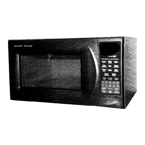
R-530BK
R-530BW
SHARP@
SERVICE MANUAL
\
'\
-i
I'
_'.
',,
S38Mi 08R530BE
MICROWAVE OVEN MODELS
R=530BK/R=530BW
In the interest of user-safety the oven is to be restored
to its original condition and only the parts identical to
those specified should be used.
R-530BK
WARNING TO SERVICE PERSONNEL: Microwave
ovens
contain
circuitry
capable of producing
very high voltage and current. Contact with the
following parts may result in a severe, possibly
fatal electrical
shock.(High
Voltage Capacitor,
High Voltage
Power Transformer,
Magnetron,
High Voltage Rectifier Assembly,
High Voltage
Harness etc..)
TABLE OF CONTENTS
SECTION
PAGE
PRECAUTIONS
TO BE OBSERVED BEFORE AND DURING SERVICE TO
AVOID POSSIBLE EXPOSURE TO EXCESSIVE MICROWAVE ENERGY. ...........
Inside Front Cover
Before Servicing
.............................................................
Inside Front Cover
Warning to Service Personnel .. : ..............................................................
1
Foreword and Warning .......................................................................
2
Specifications
...............................................................................
3
Generallnformation
.........................................................................
4
KeyUnitLayout
.............................................................................
5
Operation
..................................................................................
6
Servicing and Troubleshooting
Guide
..........................................................
9
TestProcedures
............................................................................
11
TouchControlOutline
.......................................................................
21
Component Replacement and Adjustment Procedure
...........................................
25
Microwave Measurement
Procedure
..........................................................
35
Wiring/Schematic
Diagram
..................................................................
36
Parts
.....................................................................................
41
Packing
and
Accessories
....................................................................
46
SHARP ELECTRONICS CORPORATION
Service Headquarters: Sharp Plaza, Mahwah, New Jersey, 07430-2135
Advertisement
Table of Contents

Related Manuals for Sharp R-530BK


Summary of Contents for Sharp R-530BK
- Page 1 Operation ............................Servicing and Troubleshooting Guide TestProcedures ................TouchControlOutline ............... Component Replacement and Adjustment Procedure ........... Microwave Measurement Procedure ............Wiring/Schematic Diagram ..............Parts ..................Packing Accessories ..............SHARP ELECTRONICS CORPORATION Service Headquarters: Sharp Plaza, Mahwah, New Jersey, 07430-2135...
- Page 2 If the unit operates with the door open, service person should 1) tell the user not to operate the oven and 2) contact SHARP ELECTRONICS CORPORATION and DHHS immediately. Service personnel should inform SHARP ELECTRONICS CORPORATION of any certified unit found with emissions in excess of 4mWcm2. The owner of the unit should be instructed not to use the unit until the oven has been brought into compliance.
- Page 3 Removal of the outer case cabinet gives access to volt- age above 25OV. All of the parts marked “A” on parts list may cause undue microwave exposure, by themselves, or when they are damaged, loosened or removed. Sharp Electronics Corporation Sharp Plaza Mahwah, New Jersey 0743012135...
-
Page 4: Before Servicing
R-530BK R-530BW Microwave ovens contain circuitry capable of producing very high voltage and current. Con- tact with following parts may result in a severe, possibly fatal, electrical shock. (EXAMPLE) High Voltage Capacitor, High Voltage Power Transformer, Magnetron, High Voltage Rectifier Assembly, High Voltage Harness etc.. -
Page 5: Specifications
R-530BK R-530BW SPECIFICATIONS Description Item Power Requirements 120 Volts 14.0 Amperes 1650 Watts 60 Hertz Single phase, 3 wire grounded Power Output 1100 watts (IEC-705 Test Procedure) Operating frequency of 2450 MHz Width 23.94” Case Dimensions Height 13.27” (including feet) Depth 19”... -
Page 6: Grounding Instructions
R-530BK R-530BW GENERAL INFORMATION Grounding Instructions Grounded This oven must be fully grounded at all times. This Grounded Receptacle Box Receptacle Box appliance must be connected to a 120 volt, 60 Hz, AC only, 15 Ampere or more fused electrical supply. It is rec-... -
Page 7: Key Unit Layout
R-530BK R-530BW Key Unit Layout Indicators. Lighted digital display. Custom Help. Features user friendly communications during cooking procedure. SENSOR COOKING pads. Cooking time is determined by AH Sensor Minute Plus pad. Touch to start oven or Touch to cook for 1 minute at 100% power or to increase cook- ing time. -
Page 8: Operation
R-530BK R-530BW OPERATION Description of Operating Sequence The following is a description of component functions interlock relay and is mechanically associated with during oven operation: the door so that it functions as follows: Off Condition When the door opens from a closed position, the... -
Page 9: Sensor Cooking Condition
R-530BK R-530BW OPERATION DESCRIPTION OF OPERATING SEQUENCE The followin g is a descri ption of corn ponent functions during oven operation. Sensor Cooking Condition When using the REHEAT function, the foods are cooked without figuring time, power level or quantity. When the... -
Page 10: Description And Function Of Components
R-530BK R-530BW DESCRIPTION AND FUNCTION OF COMPONENTS Cooling Fan Motor Monitor Switch The monitor switch is activated (the contacts opened) by The cooling fan motor drives a blade which draws exter- the latch head on the door while the door is closed. The nal cool air. -
Page 11: Troubleshooting Guide
R-530BK R-530BW When troubleshooting the microwave oven, it is helpful to follow the sequence of operation in performing the checks. Many of the possible causes of trouble will require that a specific test be performed. These tests are given a procedure letter which will be found in the “Test Procedure”... - Page 12 R-530BK R-530BW Troubleshooting Guide Cook Condition Test Procedure Problem Possible Cause Oven lamp does not light at all. Shorted or open wiring Check or replace Oven lamp or socket Check or replace Control unit Procedure G Oven lamp lights, but fan motor and...
-
Page 13: Test Procedures
TEST PROCEDURES Procedure Letter Component Test Magnetron Assembly Test 1. Disconnect the power supply cord, and then remove outercase cabinet. 2. Open the door and block it open. 3. Discharge the high voltage capacitor. 4. To test for an open filament, isolate the magnetron from the high voltage circuit. A continuity check across the magnetron filament leads should indicate less than IQ. - Page 14 R-530BK R-530BW Procedure Letter Component Test High Voltage Rectifier Test 1. Disconnect the power supply cord, and then remove outer case cabinet. 2. Open the door and block it open. Discharge the high voltage capacitor. Isolate the rectifier from the circuit. Using the highest ohm scale of the meter, read the resistance across the terminals and observe, reverse the leads to the rectifier terminals and observe meter reading.
-
Page 15: Primary Interlock Relay (Ry-2)
R-530BK R-530BW Component Test Procedure Letter Continued Primary Interlock Relay (RY-2) 1. Disconnect the power supply cord, and then remove outer case cabinet. 2. Open the door and block it open. 3. Discharge the high voltage capacitor. 4. Disconnect two (2) wire leads from the relay on the printed circuit board in the control panel assem- bly. -
Page 16: Touch Control Panel Assembly Test
R-530BK R-530BW Procedure Letter Component Test Continued Open Monitor Fuse 1. Disconnect the power supply cord, and then remove outer case cabinet. 2. Open the door and block it open. 3. Discharge the high voltage capacitor. 4 If the monitor fuse is open, perform the tests for the primary interlock system, secondary interlock switch and the monitor switch according to the procedure outlined in this section. - Page 17 R-530BK R-530BW Procedure Letter Component Test Continued Touch Control Panel Assembly Test 1. Key Unit 1. Disconnect the power supply cord, and then remove outer case cabinet 2. Open the door and block it open. 3. Discharge the high voltage capacitor.
-
Page 18: Relay Test
R-530BK R-530BW TEST PROCEDURES Procedure Letter Component Test Relay Test Disconnect the power supply cord, and then remove outer case cabinet. Open the door and block it open. Discharge the high voltage capacitor. Disconnect the leads to the primary of the power transformer. - Page 19 R-530BK R-530BW Component Test Procedure Letter Continued Procedures to be taken when the foil pattern of the printed wiring board (PWB) is open Make a visual inspection of the varistor burn damage and test the transformer with an ohm- meter for the presence of layer short-circuit (check the primary coil resistance which is approximately 210 Q &...
-
Page 20: Compu Defrost Test
R-530BK R-530BW Procedure Letter Component Test Compu Defrost Test 1. Place one cup of water in the center of the turntable tray in the oven cavity. 2. Close the door, touch the”COMPU DEFROST” pad twice and touch the number pad “I”, and touch the number pad “5”. -
Page 21: Testing Method For Ah Sensor And/Or Control Unit
TEST PROCEDURES Component Test Procedure Letter AH Sensor Test Checking the initial sensor cooking condition 1. The oven should be plugged in at least five minutes before sensor cooking. 2. Room temperature should not exceed 95” F (35” C). 3. The unit should not be installed in any areas where heat and steam are generated. The unit should not be installed, for example, next to a conventional surface unit. - Page 22 R-530BK R-530BW Procedure Letter Component Test Checking the Control Unit (Continued) 6. Disconnect the wire leads to the primary of power transformer. 7. Ensure that these leads remain isolated from other components and oven chassis by using insu- lated tape.
-
Page 23: Outline Of Touch Control Panel
R-530BK R-530BW OUTLINE OF TOUCH CONTROL PANEL The touch control section consists of the following units emit Audible sounds (key touch sound and comple- as shown in the touch control panel circuit: tion sound). (1) Key Unit Door Sensing Switch (2) Control Unit (The Control Unit consist of Power Unit A switch to “tell”... -
Page 24: Description Of Lsi
R-530BK R-530BW DESCRIPTION OF LSI The I/O signals of the LSI (IZA866DR) is detailed in the following table. Pin No. Signal Description Signal coming from touch-key. When either G-12 line on key matrix is touched, a corresponding signal out of P20-P27 will be input into AN8. - Page 25 R-530BK R-530BW Pin No. Signal Description Signal to sound Buzzer (2.0 kHz). 0.1 sec. Terminal not used. Common data signal: COM5. Connected to LCD signal COM5 (Pin No. 37). 25-29 P33-P37 Segment data signal. Connected to LCD. The relation between signals are as follows: LSI signal (Pin No.)
- Page 26 R-530BK R-530BW Pin No. Signal Description 80-84 PIO-PI4 Used for Initial balancing of the bridge circuit (absolute humidity sensor). P15-PI6 Terminal not used. 85-86 Oven lamp, fan motor and turntable motor driving signal. To turn on and off shut off relay RYI.
- Page 27 R-530BK R-530BW SERVICING Precautions for Handling Electronic the two can’t be separated. For those models, check and repair all the controls (sensor-related ones in- Components cluded) of the touch control panel while keeping it This unit uses CMOS LSI in the integral part of the cir- connected to the oven.
- Page 28 R-530BK R-530BW COMPONENT REPLACEMENT/ADJUSTMENT PROCEDURE icrowave ovens contain circuitry capable of producing very high voltage and current, contact with the following arts may result in severe, possibly fatal, electric shock. (ample igh Voltage Capacitor, Power Transformer, Magnetron, High Voltage Rectifier Assembly, High Voltage Harness Avoid possible exposure to microwave energy.
-
Page 29: Component Replacement / Adjustment Procedure
R-530BK R-530BW COMPONENT REPLACEMENT / ADJUSTMENT PROCEDURE Please refer to “OVEN PARTS, CABINET PARTS, CONTROL PANEL PARTS, DOOR PARTS” When carrying out any of the following removal procedures: Outer Case Removal left portion of rear cabinet using a T20H Torx type or GTXH20-100 screw driver. -
Page 30: Control Panel Assembly Removal
R-530BK R-530BW COMPONENT REPLACEMENT / ADJUSTMENT PROCEDURE Magnetron Installation with care to prevent damage to the magnetron tube. 2. Secure the magnetron with four (4) screws. 3. Hold the chassis support to the magnetron and mag- When replacing the magnetron, be sure that the R.F. -
Page 31: Cooling Fan Motor Removal
R-530BK R-530BW COMPON’ENT REPLACEMENT / ADJUSTMENT PROCEDURE Turntable Motor Re-install Remove any sharp edges on the turntable motor 3. Secure motor cover with one (1) screw to base plate. cover and the base plate with cutting pliers. Insert the edge of motor cover into tab on the base plate. -
Page 32: Door Sensing Switch /Secondary Interlock Switch And Monitor Switch Removal
R-530BK R-530BW Door Sensing Switch /Secondary Interlock Then check lower portion of the latch hook, by pushing and pulling the lower portion of the door toward the Switch and Monitor Switch Adjustments oven face. Both results (play of the door) should be Disconnect the power supply cord and remove outer less than 0.5mm. - Page 33 R-530BK R-530BW Removal After adjustment, make sure of the following: Door latch heads smoothly catch latch hook through Disconnect the power supply cord. latch holes, and also latch head goes through the cen- Push the open button and open the door slightly.
-
Page 34: Absolute Humidity Sensor Circuit
R-530BK R-530BW ABSOLUTE HUMIDITY SENSOR CIRCUIT the sensor cooking of the unit. Structure of Absolute Humidity Sensor When the unit is set in the sensor cooking mode, 16 sec- The absolute humidity sensor includes two thermistors onds later the detector circuit starts to function and the as shown in the illustration. -
Page 35: Ah Sensor Duct Removal
R-530BK R-530BW AH SENSOR DUCT REMOVAL Disconnect the power supply cord. Slide the two tabs of the sensor duct to the right. Open the oven door and block it open. Sensor duct is now free. Remove screws from the rear of the outercase cabi- net. - Page 36 R-530BK R-530BW AH SENSOR ORIENTATION & HARNESS ROUTING AH Sensor Orientation Mounting, Screw AH Sensor Duct AH densor Figure 1-I 6 Oven Left Side View AH Sensor Harness Figure 2-16 Oven Top View...
-
Page 37: Interlock Switch Test
R-530BK R-530BW MICROWAVE MEASUREMENT PROCEDURE After adjustment of the door, interlock and monitor 2. Place the oven tray in the oven cavity. switches are completed individually or collectively, a IN- 3. Place the load of 275 Z!I 15ml(9.8 oz.) of tap water ini-... - Page 39 R-530BK R-530BW - - - - - 00’ ’ - - -...
- Page 40 R-530BK R-530BW -[c10~ R4 27 Q2 2SB1238 Dl -D4 +-+t-b+- AC1 2OV 60Hz BUZZER TURNTABLE MOTOR OVEN LAMP R6 3.3k -em-_ MOTOR TURNTABLE MOTOR OVEN LAMP MOTOR Q3 KRC243M MICRO MICRO N.C. N.C. DOOR SWITCH DOOR SWITCH NOTE IF NOT SPECIFIED, 1/4w + 5% .-+--...
- Page 41 R-530BK R-530BW --’ YSl P9tl YSlE9tl YSl z9tl YL’P Sltl OS/w0 at- i -----_- ’ > AOSlrll’O 113 ‘I...
- Page 42 Printed Wiring Board of Power Unit...
-
Page 43: Parts List
R-530BK R-530BW PARTS LIST Contact your nearest SHARP Parts Distributor to order. For location of SHARP Parts Distributor, Please call Toll-Free; I-800-BE-SHARP Ref No. Part No. Description Code Electrical l- 1 RC-QZBOl8MREO H.V. Capacitor l- 2 FH-DZB008MRYO H.V. Diode assembly... -
Page 44: Control Panel
R-530BK R-530BW Ref No. Part No. Description Code Control Panel CPWBFBO12MRUO Control unit 3-1A QCNCMA275DREO 2-pin connector (CN-A) 3-1B QCNCMA275DREO &pin connector (CN-B) 3-1c (WH-1) FW-VZB146MREO Lead wire harness RC-KZAO87DREO Capacitor O.lpF 50V VCEAB31EW108M Capacitor 1000pF 35V RC-KZA087DREO Capacitor O.lpF 50V... - Page 45 R-530BW Description Ref No. Part No. Code Door CDORFB183MRKO Door assembly (R-53OBK) CDORFB193MRKO Door assembly(R-530BW) ’ FCOV-BO94MRKOA Door screen assembly(R-530BK) FCOV-B114MRKOA Door screen assembly (R-53OBW) Door panel FDORFB049MRTO 4- 3 PSHEPBOlGMREO Sealer film 4- 4 GCOVHB028MRFO Choke cover 4- 5...
-
Page 46: Cavity Assembly
R-530BK R-530BW Cavity Assembly #’ \‘ ‘/’ 6-12 2-16 > 8... -
Page 47: Control Panel Assembly
R-530BK R-530BW Control Panel Assembly [’ I’I::: Door Assembly ---- ------- ------- r----... -
Page 48: Wire Harnesses
R-530BK R-530BW Wire Harnesses *Actual harnesses may be different than illustrations. Packing and Accessories TURNTABLE SUPPORT * TRAY PACK * PACKING CASE * Non-replaceable items. ‘980 SHARP CORP. (4M2.70E) Printed in U.S.A.
Need help?
Do you have a question about the R-530BK and is the answer not in the manual?
Questions and answers