
Related Manuals for Net Safety MILLENNIUM II

Summary of Contents for Net Safety MILLENNIUM II
- Page 1 MILLENNIUM II Multi-Channel Transmitter User Manual Single or Dual Channel Part Number: MAN-0076 Rev Aprl Part Number: MAN-0076 Rev 04 August 25, 2010 2008...
-
Page 2: Important Information
Monitoring Inc. Contact Net Safety Monitoring Inc. or an authorized representative for details. We welcome your input at Net Safety Monitoring. If you have any comments please contact us at the phone/ address below or visit our web site and complete our on-line customer survey: www.net-safety.com/... -
Page 3: Table Of Contents
4.2.4 Viewing and setting alarm levels (points) ........................27 4.2.5 Setting Relay options ............................... 28 4.2.6 Relay Assignment ................................28 4.2.7 Relay Alarm Mode setting (for Oxygen sensors only) ..................... 30 MAN-0076 Rev 4 Millennium II August 25, 2010 Net Safety Monitoring Inc... - Page 4 APPENDIX ....................................... 43 APPENDIX A: ELECTROSTATIC SENSITIVE DEVICE (ESD) ..................... 43 APPENDIX B: RESISTANCE TABLE ............................44 APPENDIX C: MILLENNIUM II TRANSMITTER SPECIFICATIONS ................45 MAN-0076 Rev 4 Millennium II August 25, 2010 Net Safety Monitoring Inc...
-
Page 5: Introduction
TX-M2a-b, Millennium II Transmitter Electronics module only (w/o enclosure): 1. If the Millennium II Transmitter is installed as Category 3 equipment, then it shall be installed in an Enclosure which maintains an ingress protection rating of IP54 and meets the enclosure requirements of EN 60079-0. -
Page 6: Enclosure Dimensions
Enclosure Dimensions The Millennium II Transmitter enclosure is available in Aluminum (AL6061) and Stainless Steel (SS316). Dimensions are in inches and millimeters. Figure 1: Transmitter Enclosure Dimensional Drawing MAN-0076 Rev 4 Millennium II August 25, 2010 Net Safety Monitoring Inc... -
Page 7: Section 1: Installation
Carefully remove all components from the packaging and check them against the enclosed packing list. Inspect all components for obvious damage such as broken or loose parts. If you find any components missing or damaged, notify the representative or Net Safety Monitoring, immediately. 1.2 Mounting Ensure transmitter and sensor are securely mounted, taking into consideration all requirements. -
Page 8: Transmitter Electronics Module And Relay Options
4-20 +Vdc Sig A A3NO normally open Sig B A3COM common ALARM FCOM Shld A3NC normally closed A1NO A1COM A1NC A2NO A2COM A2NC A3NO A3COM A3NC MAN-0076 Rev 4 Millennium II August 25, 2010 Net Safety Monitoring Inc... -
Page 9: Rotating Electronics Module Relative To Enclosure And Conduit Entries
Refer to Appendix A, “Electrostatic Sensitive Device (ESD)”. Figure 4: Rotating Electronics module Note: To access enclosure grounding screw, remove the electronics module by following steps 1-7 above. MAN-0076 Rev 4 Millennium II August 25, 2010 Net Safety Monitoring Inc... -
Page 10: Section 2: Wiring And Installation
Seals are especially recommended for installations that use high-pressure or steam cleaning devices in proximity to the transmitter and/or sensor. The cementing material used on the Millennium II sensors is suitable for an operating temperature range of (-55°C to +85 °C). Guidelines •... -
Page 11: Cable Choice And Guidelines
Figure 5. This cable should be used between the PLC/PANEL/DCS and the Millennium II Transmitter, as well as between the Millennium II Transmitter and junction box. Additional notes: In general, communication cables and power cables should not run in parallel for any significant length, and should not be carried in the same cable tray. - Page 12 (Green wire) connected to Earth grounding ¾” NPT stopping screw in junction box plug. Note: If required, use cable glands which have been approved for hazardous locations. MAN-0076 Rev 4 Millennium II August 25, 2010 Net Safety Monitoring Inc...
-
Page 13: Analog Output, Isolated Supply, Non-Isolated Supply And Jumper Configuration
Figure 7: Non- Isolated and Isolated current jumpers Warning Always ensure that JP3 and JP4 jumpers are in the correct position depending on the current output configuration chosen. MAN-0076 Rev 4 Millennium II August 25, 2010 Net Safety Monitoring Inc... -
Page 14: Remotely Mounted Sensors Jumper Configuration
Jumpers and pins are located on the main terminal board near the sensor terminals. JP1 is for channel 1 and JP2 is for channel 2. Refer to Figure Figure 8: Separation Jumpers positions Warning When separating sensor and transmitter, install JP1 and JP2 over pins. MAN-0076 Rev 4 Millennium II August 25, 2010 Net Safety Monitoring Inc... -
Page 15: Sensor And Transmitter Terminals
4-20(CH1) Current loop output Green Earth Ground ISO(CH1) +Vdc isolated 4-20 power 4-20(CH2) Current loop output ISO(CH2) +Vdc isolated 4-20 power Figure 9: Sensor wiring and terminal connections MAN-0076 Rev 4 Millennium II August 25, 2010 Net Safety Monitoring Inc... -
Page 16: Remote Reset
2000ft using 16 AWG wire. See Appendix B for information on wire gauge and resistance. Figure 11: Sensor separation/remote mounting of sensor MAN-0076 Rev 4 Millennium II August 25, 2010 Net Safety Monitoring Inc... -
Page 17: Wiring Drawings
2.1.8 Wiring drawings Wiring drawings show general ways in wiring the system for analog signal output. Consult qualified personnel on specific wiring requirements. Figure 12: Non-isolated terminal connection MAN-0076 Rev 4 Millennium II August 25, 2010 Net Safety Monitoring Inc... - Page 18 Figure 13: Isolated terminal connection MAN-0076 Rev 4 Millennium II August 25, 2010 Net Safety Monitoring Inc...
-
Page 19: Installation Checklist
Check wiring at all termination and junction points; wiring at transmitter terminals, junction box and at power supply. Refer to Table 1, also Figure Figure 8 Figure 9 MAN-0076 Rev 4 Millennium II August 25, 2010 Net Safety Monitoring Inc... -
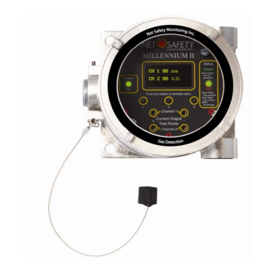
Page 20: Section 3: Transmitter And Faceplate Description
3.2 Display The Millennium II is equipped with an Organic LED (O LED) display. It allows the user to see the concentration of gas present for each individual channel and the various options offered. The display has a wide temperature rating and will operate well in lowly lit conditions. -
Page 21: Status Led
Intrusive (keeping the enclosure closed and using the magnet and reed switches). 3.5.1 Intrusive Access The menu buttons provide access to the Millennium II’s Main Menu options allowing the user to review and configure existing options under sub menus and perform calibration. There are three visible main menu buttons that are located directly under the display screen. -
Page 22: Section 4: Operation
Select menu button 1 or 2 Select “Yes” by to scroll/navigate through selecting menu Enter main menu? Calibrate Sensor? main menu button 1 Menu buttons/ Menu buttons/ Switches Switches MAN-0076 Rev 4 Millennium II August 25, 2010 Net Safety Monitoring Inc... - Page 23 3. See page 31). (Activate menu button 3 to display Calibrate sensor. sub menu) (Activate menu MAN-0076 Rev 4 Millennium II button 3 to display August 25, 2010 sub menu) Net Safety Monitoring Inc Activate button 2 Activate button 1...
-
Page 24: Full Calibration (Normal Calibration) Procedure
The following calibration procedure should be followed to ensure an accurate correlation between the output signal and the gas concentration. For accurate performance, the Millennium II is calibrated using 50% span gas. The transmitter will however, allow some flexibility in the use of calibration gas with some sensors; calibration gas outside of 50 % span (10% - 60% span gas) will be allowed on specific sensor models (see specific sensor manual for details). -
Page 25: Cont'd) Zero Calibration Option
The cup doesn’t have to be removed for normal operation. When the cup is in place, inject calibration gas at a rate of 0.5 – 1.0 liter per minute. MAN-0076 Rev 4 Millennium II August 25, 2010 Net Safety Monitoring Inc... - Page 26 Apply air from canister FULL Calibration ZERO calibration or use clean ambient Note: *Calibration process is similar if calibration of channel 2 is required. MAN-0076 Rev 4 Millennium II August 25, 2010 Net Safety Monitoring Inc...
-
Page 27: Enable / Disable Channels
4.2.3 Enable / Disable channels This option allows the Millennium II Transmitter channels to be enabled or disabled. The default value is channel 1(CH1) enabled for single sensor models while channel 2(CH2) is permanently disabled. Both channels are enabled for two sensor models. -
Page 28: Setting Relay Options
Note 2: Prior to assigning relays, configure the alarm levels (points). See Section ‘4.2.4 Viewing and setting alarm levels (points)’, and then follow the steps and example below to configure the Alarm relays. Also see Table Example and Table MAN-0076 Rev 4 Millennium II August 25, 2010 Net Safety Monitoring Inc... - Page 29 Under the specific relay with channel, activate the enter key (switch 3) to choose the appropriate setting. See Table 3 below. Table 3 : Available Millennium II Relay Options Relays and Assignment Options ALARM RELAY 1 (RL1) ALARM RELAY 2 (RL2)
-
Page 30: Relay Alarm Mode Setting (For Oxygen Sensors Only)
Table 4: Typical Millennium II Relay Configurations Relay Assignment Example Channel # and selected ALARM RELAY 1 (RL1) ALARM RELAY 2 (RL2) ALARM RELAY 3 (RL3) Alarm points (levels) RL1:CH1 RL2:CH1 RL3:CH1 POINT 1=20% lel POINT 1=20% lel Disabled POINT 2=40% lel... -
Page 31: Setup Current Date
1. Enter the main menu by activating any key to get the “enter main menu” prompt, then activate switch 1 to select “yes.” 2. Activate the up key (switch 1) or down (switch 2) until “Setup Current Time?” option is displayed. MAN-0076 Rev 4 Millennium II August 25, 2010 Net Safety Monitoring Inc... -
Page 32: View Event Log
“Exit” at each menu stage (sub menu and main menu). 4.3.2 View Event Log The Millennium II Transmitter has the ability to store up to 980 events. Events can be viewed by navigating through this menu option. The most recent events are shown first. -
Page 33: Manual Reset
“Relay Test Complete” will be displayed. See steps to initiate relay self test below. Proper functioning electromechanical relays have a clicking sound during this test. If the Millennium II Transmitter is equipped with Solid State relays, then an Ohm meter must be used to check the changes in resistance values between contacts. -
Page 34: Select Gas Type
4.3.8 Serial Number & Firmware Version This option is used when the serial number or firmware version of the Millennium II Transmitter is required. 1. Enter the main menu by activating any key to get the “enter main menu” prompt, then activate switch 1 to select “yes.”... -
Page 35: Section 5: Monitoring And Outputs
Self-testing circuitry continuously checks for problems that could prevent proper response. When power is applied to the Millennium II Transmitter, a micro controller automatically tests the system to ensure that it is functioning properly. During normal operation, it continuously monitors the signal from the internal sensor source. In addition, a “watchdog”... -
Page 36: Sensor Status Registers, Transmitter Status Led, Current Output And Meaning
See Event Log in transmitter main menu. 4 – 20 Fast Flash See Event Log in transmitter main menu. Fast Flash FAULT DETECTED: Input voltage <8V. Fast Flash FAULT DETECTED: Input voltage >33V. MAN-0076 Rev 4 Millennium II August 25, 2010 Net Safety Monitoring Inc... -
Page 37: Rs-485 Modbus Rtu
The Millennium II Transmitter utilizes 2- wire Modbus RS-485 multi serial mode. This Modbus solution implements a 2-wire electrical interface in accordance with the EIA/TIA-485 standards. For this MODBUS configuration, it is important that a third wire be used for connecting all the ‘Common’... - Page 38 RFU – Reserved for future use ** The transmitter Status register (Register 40021) is a bit flag register. Table 8 on next page, shows the detailed meaning of each bit in the register. MAN-0076 Rev 4 Millennium II August 25, 2010 Net Safety Monitoring Inc...
-
Page 39: Hart Communication
The HART protocol is a powerful communication technology enabling users to exploit the full functionality of the Millennium II Transmitter. The HART communication option is only available with the single channel version of the Millennium II Transmitter. The Millennium II Transmitter is a generic device that will work with other universal communication devices. -
Page 40: Section 6: Maintaining
Be sure to prevent unwanted response of external monitoring devices and equipment during this procedure. If the Millennium II’s response to calibration gas is within the specified accuracy then it is not necessary to perform a calibration. -
Page 41: Storage
Dual channel transmitter w/analog & solid state relay output TX-M22-AD Dual channel transmitter w/analog & digital Modbus output TX-M22-ARD Dual channel transmitter w/analog, relay & digital Modbus output MAN-0076 Rev 4 Millennium II August 25, 2010 Net Safety Monitoring Inc... -
Page 42: How To Return Equipment
Pack items to protect them from damage and use anti-static bags or Aluminum-backed cardboard as protection from electro-static discharge. ALL equipment must be shipped prepaid. Collect shipments will not be accepted. MAN-0076 Rev 4 Millennium II August 25, 2010 Net Safety Monitoring Inc... -
Page 43: Appendix
In general, exercise accepted and proven precautions normally observed when handling electrostatic sensitive devices. A warning label is placed on the packaging, identifying product using electrostatic sensitive semiconductor devices. MAN-0076 Rev 4 Millennium II August 25, 2010 Net Safety Monitoring Inc... -
Page 44: Appendix B: Resistance Table
7000 71.10 44.70 28.10 17.70 7500 76.10 47.90 30.10 19.00 8000 81.20 51.10 23.10 20.20 9000 91.40 57.50 36.10 22.70 10000 102.00 63.90 40.20 25.30 Resistance shown is one way. This figure should be doubled when determining closed loop resistance. MAN-0076 Rev 4 Millennium II August 25, 2010 Net Safety Monitoring Inc... -
Page 45: Appendix C: Millennium Ii Transmitter Specifications
Appendix C: MILLENNIUM II Transmitter Specifications Transmitter model Analog-Relay Analog Analog/HART Digital Electrical IR: <150 mA @ 24 Vdc Power Consumption (with sensor attached) Solid State( H2S or Ammonia): 100mA @24Vdc Voltage Range 10.5 – 32 Vdc 10.5 – 32 Vdc 18 –... - Page 46 TX-M2a-b, Millennium II Transmitter Electronic Module Only (w/o enclosure) Specific Conditions of Use: 1. If the Millennium II Transmitter is installed as Category3 equipment, then it shall be installed in an Enclosure which maintains an ingress protection rating of IP54 and meets the enclosure requirements of EN 50014 or EN 60079-0.
- Page 47 Net Safety Monitoring Inc. 2721 Hopewell Place NE, Calgary, AB Canada T1Y 7J7 1‐866‐FIREGAS (347‐3427) | ph. (403) 219‐0688 | fx. (403) 219‐0694 http://www.net‐safety.com | Email: nsmsales@net‐safety.com PRODUCT SERVICES CONTACT INFORMATION Telephone [ 8am ‐ 5pm MDT ]: (403) 769‐6074 | (403) 717‐8219 Fax: (403) 219‐0694 Email: productservices@net‐safety.com http://www.net‐safety.com/service/product_services.html MAN-0076 Rev 4 Millennium II August 25, 2010 Net Safety Monitoring Inc...
Need help?
Do you have a question about the MILLENNIUM II and is the answer not in the manual?
Questions and answers