Table of Contents
Advertisement
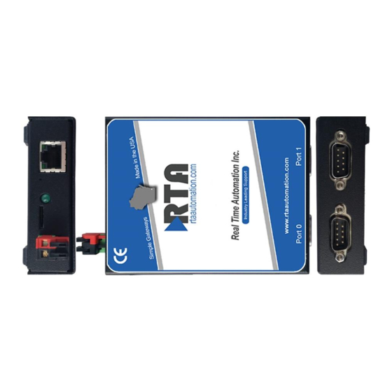
460 User Manual
Gateways for transferring data between
different protocols:
BACnet/IP
DeviceNet
EtherNet/IP
Modbus RTU
Modbus TCP
Serial
________________________________________________________________________
Real Time Automation, Inc.
150 S. Sunnyslope Rd. Suite 130
Brookfield, WI 53005
262.439.4999 (V) 262.439.4989 (F)
www.rtaautomation.com
Advertisement
Table of Contents

Related Manuals for RTA 460


Summary of Contents for RTA 460
-
Page 1: User Manual
460 User Manual Gateways for transferring data between different protocols: BACnet/IP DeviceNet EtherNet/IP Modbus RTU Modbus TCP Serial ________________________________________________________________________ Real Time Automation, Inc. 150 S. Sunnyslope Rd. Suite 130 Brookfield, WI 53005 262.439.4999 (V) 262.439.4989 (F) www.rtaautomation.com... -
Page 2: Revision History
Twido is a trademark of Schneider Electric. All other trademarks and registered trademarks are the property of their holders. Revision history Revision Revision dates Principal changes Software version 01/15/2009 First publication © 2009 Real Time Automation, Inc. All rights reserved. 460 Gateway User Manual Page i... - Page 3 Automation Repair Center. To obtain service, you must include: (a) a copy of your PO, complete RMA form found at http://www.rtaautomation.com/returns/ (b) a written description of the problem; (c) the name and location of the installation facility (if applicable) and, most importantly; (d) your address and telephone number. 460 Gateway User Manual Page ii...
- Page 4 Products associated with such Real Time Automation, Inc. software. No other use, including without limitation disassembly of such Real Time Automation, Inc. software or exercise of the exclusive rights reserved for Real Time Automation, Inc. is permitted. 460 Gateway User Manual Page iii...
-
Page 5: Table Of Contents
Uploading a configuration file to additional gateways........63 Changing IP or subnet addresses ................66 The IPSetup.exe......................66 The Real Time Automation 460 Gateway web site ..........67 Chapter 5 Panel mount dimensions................70 460 Gateway User Manual Page iv... -
Page 6: Chapter 1 Introduction
See Figure 1-1 below. The 460 Gateways are easy to configure using an embedded web page from which you enter the appropriate network addresses and then define the groups of registers to send/receive data and the order in which the data is received. -
Page 7: Specifications
Default IP Address – 192.168.0.100 Specifications Table 1-1 shows the specifications for the 460 Gateway. Table 1-1 460 Gateway specifications Item Description Hardware description Dimensions: 11 x 8.3 x 2.54 centimeters (4.2 x 3.25 x 1 inches) Weight: 5 ounces... -
Page 8: Supported Protocols
• A CD with the user manuals and utilities Additional required equipment You need to connect a personal computer to the 460 Gateway just during the initial software setup or if you need to change settings because of a device change. -
Page 9: Chapter 2 Installing The 460 Gateway
Other 460 Gateways cannot be modified to change the port settings. The default port settings on the 460 EDX Gateway are for Port 0 to be set for RS485 and Port 1 to be set for RS232. However, you can modify a port to use CAN (or return a port setting to RS 232 or RS485) by changing the jumpers on the Gateway unit. -
Page 10: Connecting A Computer For Software Setup
460 Gateway. Use the following steps to connect the computer and to access the embedded web site where you make your software selections. 1. Connect one end of the Ethernet crossover cable to the 460 Gateway and the other end to the RJ45 connector on your computer. - Page 11 Default IP Address – 192.168.0.100 2. Insert the power connector to the 460 gateway unit, and then plug the power cord into a power source. 3. Launch the web browser. In the address window, enter http://192.168.0.100 Press Enter The RTA 460 Gateway Main Page displays. See Figure 2-2.
- Page 12 Default IP Address – 192.168.0.100 Note: If this is not the first time that this 460 Gateway has been configured, Figure 2-2 displays different modules. Edit 4. Click on next to the on the RTA Gateway Main Page. See Description module Figure 2-2.
-
Page 13: Configuring The 460 Gateway
Default IP Address – 192.168.0.100 Configuring the 460 Gateway The 460 Gateway always acts as at least two devices at a time (for example, a Modbus RTU Master and a serial device). Therefore, you must always configure at least two Communication Modules. - Page 14 Default IP Address – 192.168.0.100 Note: The Edit buttons are grayed out when the task applies to a different 460 Gateway version than you purchased. Please contact Real Time Automation, Inc. (RTA) at 262.439.4999 or www.rtaautomation.com for more information about 460 Gateway configurations.
- Page 15 Figure 2-7 displays. Figure 2-7 Serial port incompatibility error 5. Click on Save The selections stay visible on the screen, although Communication Module Configuration Edit they are grayed out (until you select again). See Figure 2-8. 460 Gateway User Manual Page 10...
- Page 16 The order of the configuration steps do not matter as long as the communication module is enabled. Return to Main 6. Click on the button. The RTA 460 Gateway Main Page displays with a Client Module Configuration option. See Figure 2-9. Figure 2-9 Modbus RTU Master Client Module Configuration Edit 7.
- Page 17 . The Master and Client Module External Device List re-displays with the Save information entered for that Device Buffer. See Figure 2-11. To add another Device Buffer, click on the button and then edit that buffer’s Add Remote Modbus RTU Slave settings. 460 Gateway User Manual Page 12...
-
Page 18: Modbus Rtu Slave Configuration
The RTA 460 Gateway Main Page displays. Modbus RTU Slave configuration If your version of the 460 Gateway requires your gateway to act as a Modbus RTU Slave, use the following steps to configure the gateway. At least two Communication Modules must be configured. - Page 19 Default IP Address – 192.168.0.100 Figure 2-12 Communication Module Configuration screen Edit 2. Click on next to Modbus RTU Slave prompt displays. See Figure 2-13. Enabled? Figure 2-13 Enable Modbus RTU Slave configuration 460 Gateway User Manual Page 14...
- Page 20 The selections stay visible on the screen, although Communication Module Configuration Edit they are grayed out. See Figure 2-16. To change these settings, click on next to again to make any necessary changes. Modbus RTU Slave 460 Gateway User Manual Page 15...
- Page 21 For Your Information: Familiar users can make all desired communication module edits before leaving this screen. Return to Main 6. Click on the button. The RTA 460 Gateway Main Page displays with the updated Modbus RTU Slave information. See Figure 2-17. Figure 2-17 Modbus RTU Slave Module Configuration...
-
Page 22: Modbus Tcp Client Configuration
Default IP Address – 192.168.0.100 Modbus TCP Client configuration If your version of the 460 Gateway requires your gateway to act as a Modbus TCP Client, use the following steps to configure the gateway. At least two Communication Modules must be configured. Edit 1. - Page 23 For Your Information: Familiar users can make all desired communication module edits before leaving this screen. Return to Main 5. Click on the button. The RTA 460 Gateway Main Page displays with a Client Module Configuration option. See Figure 2-21. 460 Gateway User Manual Page 18...
- Page 24 External Device Configuration screen 7. For each new Device Buffer that should be enabled (1-32), click on the Add Remote button. Modbus TCP Server 8. Click in the column. See Figure 2-23. Edit Action 460 Gateway User Manual Page 19...
- Page 25 Device Buffer. See Figure 2-24. To add another Device Buffer, click on the button and then edit that buffer’s Add Remote Modbus TCP Server settings. Figure 2-24 Modbus TCP Client data selections 460 Gateway User Manual Page 20...
-
Page 26: Modbus Tcp Server Configuration
The RTA 460 Gateway Main Page displays. Modbus TCP Server configuration If your version of the 460 Gateway requires your gateway to act as a Modbus TCP Server, use the following steps to configure the gateway. At least two Communication Modules must be configured. - Page 27 Default IP Address – 192.168.0.100 Figure 2-25 Communication Module Configuration screen Edit 2. Click on next to Modbus TCP Server prompt displays. See Figure 2-26. Enabled? Figure 2-26 Enable Modbus TCP Server configuration 460 Gateway User Manual Page 22...
- Page 28 For Your Information: Familiar users can make all desired communication module edits before leaving this screen. Return to Main 5. Click on the button. The RTA 460 Gateway Main Page displays with the updated Modbus TCP Server information. See Figure 2-27. Figure 2-27 Modbus TCP Server Configuration...
-
Page 29: Ethernet/Ip Client Configuration
Default IP Address – 192.168.0.100 EtherNet/IP Client configuration If your version of the 460 Gateway requires your gateway to act as an EtherNet/IP Client, use the following steps to configure the gateway. At least two Communication Modules must be configured. Edit 1. Click on... - Page 30 The Module’s Detail options expand when enabled. See Figure 2-30. Figure 2-30 EtherNet/IP Client configuration details 4. Click on Save For Your Information: Familiar users can make all desired communication module edits before leaving this screen. 460 Gateway User Manual Page 25...
- Page 31 Default IP Address – 192.168.0.100 Return to Main 5. Click on the button. The RTA 460 Gateway Main Page displays with a Client Module Configuration option. See Figure 2-31. Figure 2-31 EtherNet/IP Client Module Configuration Edit 6. Click on next to the Client Module Configuration screen displays.
-
Page 32: Ethernet/Ip Server Configuration
The RTA 460 Gateway Main Page displays. EtherNet/IP Server configuration If your version of the 460 Gateway requires your gateway to act as an EtherNet/IP Server, use the following steps to configure the gateway. At least two Communication Modules must be configured. - Page 33 Main Page. See Figure 2-2. screen displays. See Figure 2-34. Communication Module Configuration Note: The Edit buttons are grayed out when the task applies to a different 460 Gateway version than you purchased. Please contact Real Time Automation, Inc. (RTA) at 262.439.4999 or www.rtaautomation.com...
- Page 34 For Your Information: Familiar users can make all desired communication module edits before leaving this screen. Return to Main 5. Click on the button. The RTA 460 Gateway Main Page displays with the updated EtherNet/IP Server information. See Figure 2-36. 460 Gateway User Manual Page 29...
-
Page 35: Devicenet Master Configuration
Default IP Address – 192.168.0.100 Figure 2-36 EtherNet/IP Server Configuration DeviceNet Master configuration If your version of the 460 Gateway requires your gateway to act as a DeviceNet Master, use the following steps to configure the gateway. At least two Communication Modules must be configured. Edit 1. - Page 36 DeviceNet Master prompt displays. See Figure 2-38. Enabled? Figure 2-38 Enable DeviceNet Master configuration 3. Click on the checkbox. Enabled? The Module’s Detail options expand when enabled. See Figure 2-39. 460 Gateway User Manual Page 31...
- Page 37 The order of the configuration steps do not matter as long as the communication module is enabled. Return to Main 6. Click on the button. The RTA 460 Gateway Main Page displays with a Client Module Configuration option. See Figure 2-41. 460 Gateway User Manual Page 32...
- Page 38 9. Enter the slave’s MAC ID and the Assembly Length for Data In and Data Out. 10. Select . The Master and Client Module External Device List re-displays with the Save information entered for that Device Buffer. See Figure 2-43. To add another Device 460 Gateway User Manual Page 33...
-
Page 39: Devicenet Slave Configuration
The RTA 460 Gateway Main Page displays. DeviceNet Slave configuration If your version of the 460 Gateway requires your gateway to act as a DeviceNet Slave, use the following steps to configure the gateway. At least two Communication Modules must be configured. - Page 40 Default IP Address – 192.168.0.100 Figure 2-44 Communication Module Configuration screen Edit 2. Click on next to DeviceNet Slave prompt displays. See Figure 2-45. Enabled? 460 Gateway User Manual Page 35...
- Page 41 The selections stay visible on the screen, although Communication Module Configuration Edit they are grayed out. See Figure 2-47. To change these settings, click on next to again to make any necessary changes. DeviceNet Slave 460 Gateway User Manual Page 36...
- Page 42 For Your Information: Familiar users can make all desired communication module edits before leaving this screen. Return to Main 6. Click on the button. The RTA 460 Gateway Main Page displays with the updated DeviceNet Slave information. See Figure 2-48. Figure 2-48 DeviceNet Slave Module Configuration...
-
Page 43: Bacnet/Ip Client Configuration
Default IP Address – 192.168.0.100 BACnet/IP Client configuration If your version of the 460 Gateway requires your gateway to act as a BACnet/IP Client, use the following steps to configure the gateway. At least two Communication Modules must be configured. Edit 1. Click on... - Page 44 For Your Information: Familiar users can make all desired communication module edits before leaving this screen. Return to Main 5. Click on the button. The RTA 460 Gateway Main Page displays with a Client Module Configuration option. See Figure 2-51. 460 Gateway User Manual Page 39...
- Page 45 Default IP Address – 192.168.0.100 Figure 2-51 BACnet/IP Client Module Configuration Edit 6. Click on next to the Client Module Configuration screen displays. External Device Configuration 7. Click in the column. See Figure 2-52. Edit Action 460 Gateway User Manual Page 40...
-
Page 46: Bacnet/Ip Server Configuration
The RTA 460 Gateway Main Page displays. BACnet/IP Server configuration If your version of the 460 Gateway requires your gateway to act as a BACnet/IP Server, use the following steps to configure the gateway. At least two Communication Modules must be configured. - Page 47 Default IP Address – 192.168.0.100 Automation, Inc. (RTA) at 262.439.4999 or www.rtaautomation.com for more information about 460 Gateway configurations. Figure 2-54 Communication Module Configuration screen Edit 2. Click on next to BACnet Server prompt displays. See Figure 2-55. Enabled? 460 Gateway User Manual...
- Page 48 The selections stay visible on the screen, although Communication Module Configuration Edit they are grayed out. See Figure 2-57. To change these settings, click on next to again to make any necessary changes. BACnet Server 460 Gateway User Manual Page 43...
- Page 49 For Your Information: Familiar users can make all desired communication module edits before leaving this screen. Return to Main 6. Click on the button. The RTA 460 Gateway Main Page displays with the updated BACnet/IP Server information. See Figure 2-58. Figure 2-58 BACnet/IP Server Module Configuration...
-
Page 50: Serial Configuration (Modules 1 And 2)
Default IP Address – 192.168.0.100 Serial configuration (Modules 1 and 2) If your version of the 460 Gateway requires your gateway to act as a serial device, use the following steps to configure the gateway. If you are connecting the 460 Gateway to two different serial devices, repeat these directions to configure Serial Module 2. - Page 51 Data flow is controlled in three ways: maximum message length, receive character timeout, and delimiters. You can use any combination (or none) of these methods. For Your Information: The Device Status and Summary button on the 460 Gateway’s Main Web page displays the data messages transmitted and the method that terminated that message, which aides in troubleshooting.
- Page 52 For example, if you enter a value of 1000, the serial device sends data to the 460 Gateway every 1 second. Even if it was in the middle of the transmission, all data from the buffer is sent to the 460 Gateway.
- Page 53 For Your Information: Familiar users can make all desired communication module edits before completing the external device list for the master/client devices. The order of the configuration steps do not matter as long as the communication module is enabled. 460 Gateway User Manual Page 48...
- Page 54 Figure 2-64 Serial Module Configuration For Your Information: If you need to configure more than one 460 Gateway with the same or similar settings, it may be quicker to configure the first gateway using these directions and then save the configuration to a file to use for the other gateway units.
-
Page 55: Editing 460 Gateway Network Settings
460EDX Gateway. Other 460 Gateway versions have similar screens. See Figure 2-65. Note: If you need to change the 460 Gateway’s IP address after the initial setup, you can use either the folowing procedure or use the IPSetup tool on the CD shipped with the 460 Gateway. - Page 56 Network Setup screen 2. Enter the IP address that identifies the 460 Gateway to the network. 3. Enter the subnet mask that identifies which devices can communicate with the 460 Gateway. 4. Enter the default gateway to use if the device cannot be accessed directly.
-
Page 57: Making Settings Take Effect
Default IP Address – 192.168.0.100 Making Settings Take Effect Before any changes to the 460 Gateway’s configuration or network settings take effect, you must reboot the unit. Do this before removing power from the 460 Gateway. Use the following steps to reboot the 460 Gateway. - Page 58 If your computer is not on the same subnet, the screen does not change, as you are no longer receiving signals from the 460 Gateway. 5. If you are installing the 460 Gateway in a position that is not connected to the computer that did the software setup, disconnect the crossover cable from the 460 Gateway and from the computer.
-
Page 59: Connecting Cables
1. Mount the 460 Gateway in the desired location. 2. Connect the appropriate cable to Port 0 on the 460 Gateway and the other end to the device that matches the protocol selected for Port 0. Do the same for Port 1. Use the correct cables. -
Page 60: Chapter 3 Troubleshooting
Default IP Address – 192.168.0.100 Chapter 3 Troubleshooting After the 460 Gateway is set up, it should transmit and receive data correctly. However, if it is not working as you expect, this chapter provides the following information to help you resolve the problem. - Page 61 Use a proxy server for your LAN Step 5 Figure 3-1 460 Gateway Main Page 5. Click on Status and Summary The RTA 460 Device Summary and Status screen displays. See Figure 3-2. 460 Gateway User Manual Page 56...
- Page 62 Note: To clear out the Value Dec, Value Hex, and Description fields without Restarting the 460 Gateway, click on Reset Status Counters 7. Click on to return to the 460 Gateway Main Page. Main Page 460 Gateway User Manual Page 57...
-
Page 63: Checking For Solutions To Common Problems
Default IP Address – 192.168.0.100 Checking for solutions to common problems Use Table 3-1 to check for possible solutions to common problems. If you are unable to resolve the issue, contact Real Time Automation, Inc. (RTA) at 262.439.4999 or www.rtaautomation.com for more assistance. - Page 64 RTA 460 Communication Module Configuration screen. • The field (in the Receive Character Timeout Serial Modules) is set to 0 on the RTA 460 Communication Module Configuration screen. The message If the serial devices have sent additional data, check Waiting for displays on the that the cable(s) is fastened securely.
-
Page 65: Chapter 4 General Procedures
If you need to configure many 460 Gateways with the same or a similar configuration, the quickest and easiest way to do so is to configure the first 460 Gateway using the steps in Chapter 1, then save that configuration to a file that you can use to configure the other 460 Gateways. - Page 66 4. Launch the web browser. In the address window, enter http://192.168.0.100 Press Enter The 460 Gateway Main Page displays. See Figure 4-4. Note: If the web page does not display, check the following settings: The web page does not display when the computer is on a wireless network because of subnet selections.
- Page 67 Default IP Address – 192.168.0.100 5. Click on Utilities The Utilities screen displays. See Figure 4-5. Figure 4-5 RTA 460 Utilities screen 6. Click on Save Configuration to File The File Download window displays. See Figure 4-6 Figure 4-6 Configuration file verification...
-
Page 68: Uploading A Configuration File To Additional Gateways
Automation web site (http://192.168.0.100), skip to step 5. 1. Connect one end of an Ethernet crossover cable to the 460 Gateway and the other end to the RJ45 connector on your computer. A red Ethernet crossover cable was shipped with the 460 Gateway. - Page 69 4. Launch the web browser. In the address window, enter http://192.168.0.100 Press Enter The 460 Gateway Main Page displays. See Figure 4-8. Note: If the web page does not display, check the following settings: The web page does not display when the computer is on a wireless network because of subnet selections.
- Page 70 Restore from File 7. Click on When the configuration file has been saved to the new 460 Gateway and restarted, the 460 Gateway Main Page displays with the pre-set configuration settings. 8. To complete installing the 460 Gateway, continue with Editing 460 Gateway Network Settings on page 50 and Making Settings Take Effect on page 52.
-
Page 71: Changing Ip Or Subnet Addresses
The easiest way involves using the IPSetup.exe tool on the User Manuals and Tools CD shipped with the 460 Gateway. However, if you no longer have the CD that came with the 460 Gateway, you can still change IP or subnet addresses using the Real Time Automation 460 Gateway web site. -
Page 72: The Real Time Automation 460 Gateway Web Site
460 Gateway is the only one that displays. Note: If you don’t see the 460 Gateway on the right, the unit is not accessible, and you need to look at connections to hub, router, switches, etc. - Page 73 Press Enter The Real Time Automation 460 Gateway web page displays. See Figure 4-11. Note: If the web page does not display, check the following settings: The web page does not display when the computer is on a wireless network because of subnet selections.
- Page 74 Network Setup screen 6. Enter the IP address that identifies the 460 Gateway to the network. 7. Enter the subnet mask that identifies which devices can communicate with the 460 Gateway. 8. Enter the default gateway to use if the device cannot be accessed directly.
-
Page 75: Chapter 5 Panel Mount Dimensions
Default IP Address – 192.168.0.100 Chapter 5 Panel mount dimensions Figure 5-1 shows the panel mount dimensions for the 460 Gateway. Figure 5-1 Panel mount dimensions 460 Gateway User Manual Page 70... - Page 76 Default IP Address – 192.168.0.100 460 Gateway User Manual Page 71...
Need help?
Do you have a question about the 460 and is the answer not in the manual?
Questions and answers