Table of Contents
Advertisement
DISCLAIMER
Information in this document is subject to change without
notice. Information provided by Alpha Radio Products Inc.®
is believed to be correct and reliable.
responsibility is assumed by Alpha Radio Products, LLC.,
unless otherwise expressly taken. Companies, names, and
data used as examples are fictitious, unless otherwise noted.
No part of this document may be reproduced or transmitted
in any form or by any means, graphic, electronic, or
mechanical, for any purpose without the express permission
of Alpha Radio Products, Inc. Alpha Radio Products, Inc.
may have patents or pending patents, trademarks,
copyrights, or other property rights covering the subject
matter in this document. The furnishings of this document
does not give you license to these patents, trademarks,
copyrights, or other intellectual property, except as expressly
written in any license agreement form
A L P H A R A D I O P R O D U C T S
ALPHA 87A
O
perating
However, no
M
anual
Alpha Radio Products
6185 Arapahoe Road • Boulder, CO 80303
Phone 303.473.9232 • Fax 303.473.9660
Read this entire manual and all other publications pertaining
to the work to be performed before you install, operate, or
maintain this equipment.
instructions and precautions. Alpha Radio Products, LLC.
provides information on its products and associated hazards,
but it assumes no responsibility for the after-sale operation of
the equipment or the safety practices of the Owner or User.
See Warranty and Notices Appendix.
©Copyright 2005 by Alpha Radio Products, LLC.
All rights reserved.
Alpha 87A User Manual Rev 2.0
Practice all product safety
Page i
Advertisement
Table of Contents

Summary of Contents for Alpha Radio 87A
- Page 1 Alpha Radio Products, Inc. Alpha Radio Products, Inc. the equipment or the safety practices of the Owner or User. may have patents or pending patents, trademarks, See Warranty and Notices Appendix.
-
Page 2: Table Of Contents
ALPHA 87A Functional Configuration ALPHAMAX Firmware Principal Functional Components AlphaMax Operating Procedures Schematic Description ALPHAREMOTE Software Schematics Available SAFETY AlphaRemote Operating Procedures Installing the AlphaRemote Software How to Operate the 87A Step-by-step Procedure Pre-Tuning Procedure Page 2 Alpha 87A User Manual Rev 2.0... -
Page 3: Introduction
Equipment Shipped The Alpha 87A ships in two heavy-duty cardboard cartons. One carton holds the power transformer and weighs 43 pounds; the second carton contains the amplifier and weighs 42 pounds. Safety: Installation and Operation The Alpha 87A is designed to meet international safety standards and FCC regulations. -
Page 4: Before Installing Your Alpha 87A
CAUTION – READ THE MANUAL CAREFULLY BEFORE INSTALLING YOUR 87A. The ALPHA 87A is extremely easy to install and operate, but failure to carry out each procedure exactly as described in the manual is likely to lead to amplifier damage, which is not covered under warranty. -
Page 5: Station Engineering Considerations
Station Engineering Considerations The 87A is capable of dramatically improving the performance of your amateur station. It is important that you observe good engineering practices to achieve all the benefits of such a station in a safe and reliable manner. This section gives a few hints for important things to look for, but it is recommended that the user also consult a good source of general information such as “The Radio Amateur’s Handbook”... - Page 6 Provide for disconnection of the feed line when not in use. Air Flow It is critical that the 87A airflow is unrestricted in any way. Keep the top of the amplifier clear of any restrictions. If you are...
-
Page 7: Before Operating Your Alpha 87A
CAUTION – READ THE MANUAL CAREFULLY BEFORE OPERATING YOUR 87A. The ALPHA 87A is extremely easy to install and operate, but failure to carry out each procedure exactly as described in the manual is likely to lead to amplifier damage which is not covered under warranty. - Page 8 This will cause covered under warranty. It is important to damage to the input wattmeter & input relay. use a good lightning arrestor, and it is good practice to disconnect and ground antenna Page 8 Alpha 87A User Manual Rev 2.0...
-
Page 9: Overview Of Amplifier Capabilities
Capabilities It is extremely important to thoroughly review the Installation and Operation sections of this manual before attempting to use the ALPHA 87A. Failure to do so could result in serious damage not covered under warranty. Continuous RF Output. The Alpha 87A... - Page 10 RTTY or other “locked key” service. This is available separately from Alpha Radio Products. Capable of no more than 150 watts into a 50dB load in bypass mode. Page 10 Alpha 87A User Manual Rev 2.0...
-
Page 11: Alpha 87A Specifications
75 lb. (34kg) net. of feed through and hot switching of 150W exciter power. Switching time approximately 1ms. Note: Alpha Radio Products reserves the right to Enclosed mechanical bypass relay. change design and/or specifications without prior notice or obligation. -
Page 12: Figures 1-3 Transformer Installation
Figures 1-3 Transformer Installation Page 12 Alpha 87A User Manual Rev 2.0... -
Page 13: Unpacking And Preparing For Operation
AC power source of 190-250V, 50-60 Hz, 20-ampere capacity. It is advisable to check the actual voltage at the connector you are going to use for the Alpha 87A. Use an accurate meter such as a DMM set to AC volts. - Page 14 Inspect the connectors on the transformer to the cover removed. This could cause be sure there is nothing blocking the damage to the Alpha 87A or you. connector holes, such as pieces of shipping materials. One of the transformer’s connectors plugs into the AC power module near the top/rear of the chassis center partition, on the power supply side.
-
Page 15: Figure 4 – Inside Top View
Figure 4 – Inside Top View Page 15 Alpha 87A User Manual Rev 2.0... -
Page 16: Figure 5 – Front Panel Lowered
Figure 5 – Front Panel Lowered Page 16 Alpha 87A User Manual Rev 2.0... -
Page 17: Figure 6 - Inside Front Panel
Figure 6 - Inside Front Panel Page 17 Alpha 87A User Manual Rev 2.0... - Page 18 Figure 7 - Rear Panel Page 18 Alpha 87A User Manual Rev 2.0...
-
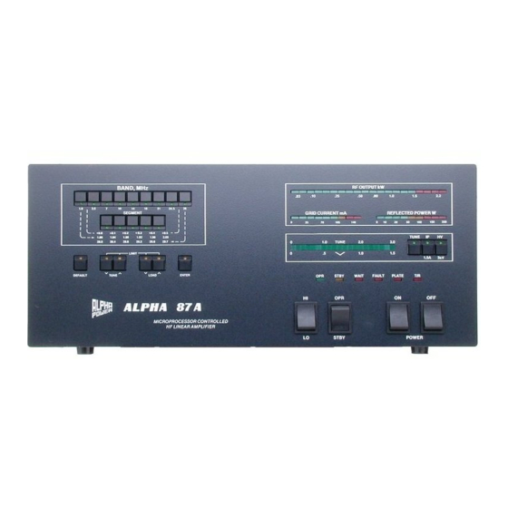
Page 19: Control And Indicator Functions
Section Control and Indicator Functions 5.1 RF OUTPUT, GRID CURRENT and 87A automatically switches bands and tunes REFLECTED POWER bargraphs are peak- up, if necessary, upon application of RF drive. reading and generally self-explanatory. BAND and SEGMENT buttons may, however, Example: 1.5 kW output (forward power into... - Page 20 ALPHA 87A will deliver 1.5 kW output (into a KEY OUT – Provides a pull-down to ground 50-ohm load of VSWR of <1.5:1) efficiently (through 47 ohm resistor) which follows the across the frequency range indicated under line connected to the RELAY jack when the that SEGMENT button.
-
Page 21: Installation
CW keyer to the RELAY jack on the 87A, and connect a cable Coaxial cable from the Alpha 87A RF from KEY OUT on the 87A to the keying input OUTPUT to antenna should be RG-8A/U, of the transmitter. - Page 22 Page 22 Alpha 87A User Manual Rev 2.0...
-
Page 23: Alphamax Tm
If you have a amplifier that was shipped from the factory prior to October Function: 1999, the installation of new chips on the 87A controller board is required. The chips to be The AlphaMax firmware upgrade enables the... - Page 24 AlphaMax may also be engaged locally by pressing the ENTER AlphaMax will attempt to tune the 87A to the button simultaneously with the LOAD^ button. optimum gain point, which results in maximum When AlphaMax is operating, the DEFAULT efficiency and lowest distortion.
-
Page 25: Alpharemote Tm Software
And it’s easy to install in any 87A; a algorithm if it was enabled. If the autotune qualified technician can do it in about 15 subroutine determines that the gain is too low, minutes. -
Page 26: Safety
SAFETY There are lethal voltages in the Alpha 87A amplifier. Special precautions must be taken to allow for the safe completion of these modifications. 1) Always unplug the amplifier from the 240 vac mains before opening the case and doing any work on your 87A. -
Page 27: Alpharemote Operating Procedures
87A or the equivalent controls with a “left click” of the mouse.The Alpha 87A must be on the Windows screen will result in AlphaMax being plugged into the AC Mains before the AlphaRemote turned of. -
Page 28: Installing The Alpharemote Software
(Note: X is the drive letter for your CD or disconnected at one end of the cable. floppy drive). 10. If AlphaRemote software is to be used with an 87A 5. To run the AlphaRemote program click START on which also has a DAS connected, the cable between... - Page 29 Select the desired configuration by clicking and holding down the left mouse button while the pointer is touching either the lower left or lower right corner of the current display and dragging the display into the desired format. Page 29 Alpha 87A User Manual Rev 2.0...
- Page 30 Page 30 Alpha 87A User Manual Rev 2.0...
-
Page 31: How To Operate The 87A
How to Operate the 87A Regardless of what frequency the ALPHA 87A was previously on, it is necessary only to apply AC power, wait 3 minutes for tube warm-up, and apply a few watts RF drive*. If driven on a band different from its existing setting the 87A automatically bypasses the transceiver output to the antenna for about one second while it change bands and tunes up. -
Page 32: Pre-Tuning Procedure
LED is positioned at the mid-scale “V” mark. Section 7.2. Heavier loading results when the LED is to the 7.1 ALC: Alpha Radio Products does not right of mid-scale, while lighter loading occurs recommend use of ALC (Automatic Level when the LED is to the left. - Page 33 Increased loading moves the TUNE LED to the right, decreased loading to the left. 5. A lighted TUNE or LOAD button LED indicates the capacitor has reached its rotational limit. Capacitor rotation is 100 steps limit-to-limit. Page 33 Alpha 87A User Manual Rev 2.0...
- Page 34 Page 34 Alpha 87A User Manual Rev 2.0...
-
Page 35: Protective Functions And "Faults
Protective Functions and “Faults” The ALPHA 87A's microprocessor-based control system constantly monitors various signals and conditions within the amplifier. If any signal or condition is detected that could cause damage or improper operation, the amplifier enters a fault condition. There are two types of faults; soft faults and hard faults. -
Page 36: Hard Faults
Six of the SAME hard fault shutdowns over ANY period of time (with no other kind of Hard fault) will then put the 87A in Fault 99 which locks it up. This function was put in the amplifier to prevent any further damage if operation was attempted after a failure had occurred. -
Page 37: Fault Codes
Excessive load reflected power or RF voltage. May be caused by excessive load VSWR at an otherwise acceptable power (e.g. 4:1 at 1.5 kW) or excessive power at otherwise acceptable load VSWR (e.g. 2.5 kW at 1.9:1). Page 37 Alpha 87A User Manual Rev 2.0... - Page 38 LOAD & LEDs Soft Control system fault; LOAD capacitor not flash initializing. LOAD & LEDs Soft Control system fault; LOAD capacitor not moving flash or zero sensor not working. Page 38 Alpha 87A User Manual Rev 2.0...
- Page 39 Unit refuses to turn on Results when the same hard fault occurs 6 consecutive times without one successful power-up. Call Alpha Customer Support at Alpha Radio Products for advice if this occurs. This fault protects the amplifier against repetitive abuse and cannot be cleared with user controls.
- Page 40 Page 40 Alpha 87A User Manual Rev 2.0...
-
Page 41: Serial Communications Link
If via an RS 232 serial communications link. you see garbage you will need to remove pin You need to use a modem communications 22 of the 25-pin end of the cable (the 87A program. example, Windows end). -
Page 42: Communications Link Set-Up
Pin 5 Make no connection from pins 9, 22, 12, 13, or 14 of the DB-25 F connector on the ALPHA 87A to the computer or terminal. These pins are used for baud rate and diagnostic modes of the unit. - Page 43 Open Open Default 4800 Open Open Open Example: To set baud rate to 9600, tie pins 12,22 and 9 to pin 7 (signal ground). View of Male Connector (pin end). Page 43 Alpha 87A User Manual Rev 2.0...
-
Page 44: Remote Commands
Used to diagnose unit with factory assistance. Use with SEG command for saving data. FREQ What frequency is the unit on or last frequency used? FREQ # (in kHz) Sets up unit for this entered frequency. Page 44 Alpha 87A User Manual Rev 2.0... - Page 45 TUNE Reports current tune capacitor setting (0-100). TUNE # (0-100) Sets tune capacitor to value entered. TUNE DOWN Sets tune capacitor down one step. TUNE UP Sets tune capacitor up one step. Page 45 Alpha 87A User Manual Rev 2.0...
- Page 46 Page 46 Alpha 87A User Manual Rev 2.0...
-
Page 47: Troubleshooting Suggestions
Assistance is available from Alpha Radio Products Customer Support at 303.473.9232, by fax at 303.473.9660, or by email at service@alpharadioproducts.com. Most apparent problems with the ALPHA 87A, especially when first putting one into operation, result directly from failure to observe carefully the procedures given in this manual, especially those repeated as cautions on pages 1 and 2 of the manual and on the handy quick-reference card provided. -
Page 48: Repeated Power-Off Shutdowns
In this case, (refer to Figure 7, p. 18) connect shutdown may be accompanied by a modest the transceiver ALC input to the ALPHA 87A’s “thump.” Usually this is the result of internal phone-type ALC jack with a shielded cable. - Page 49 4. Fault 22: This is a typical result of incorrect transformer installation, (e.g., a connector not properly mated and seated.) Page 49 Alpha 87A User Manual Rev 2.0...
- Page 50 Page 50 Alpha 87A User Manual Rev 2.0...
-
Page 51: Alpha 87A Functional Configuration
However, its basic functional organization is quite easily understood from the following: Figure 8 (page 37) is a simplified block diagram of the ALPHA 87A, and Figure 9 (page 38) is a simplified schematic showing the principal RF signal paths and primary AC power circuits. -
Page 52: Schematic Description
Schematics Available One set of current Alpha 87A schematics will be provided at no charge to any owner on request, and assistance with specific questions or problems is always available from Alpha Power Customer Support. - Page 53 Page Number 1.-3. Transformer installation Inside top view View with front panel lowered Front panel view Rear panel view Examples of AlphaRemote screen configurations ALPHA 87A Functional block ALPHA 87A Simplified schematic Page 53 Alpha 87A User Manual Rev 2.0...
- Page 54 In the absence of an Alpha Radio Products sales receipt the term of the four-year warranty will be assessed by the unit’s construction date.
Need help?
Do you have a question about the 87A and is the answer not in the manual?
Questions and answers