Table of Contents
Advertisement
Advertisement
Table of Contents

Related Manuals for Alpha Power 99


Summary of Contents for Alpha Power 99
-
Page 1: Power Amplifier
MODEL Operating Manual Alpha 99 Power Amplifier... - Page 2 Manual Alpha 99 Rev 1.doc...
- Page 3 A L P H A P O W E R P R O D U C T S LPHA 99 perating anual Warnings posted in this manual should be read and thoroughly understood by users. Failure to perform procedures properly may result in amplifier damage, fire hazard, or electric shock.
- Page 4 DISCLAIMER Information in this document is subject to change without notice. Information provided by Radio Alpha Products Inc.® is believed to be correct and reliable. However, no responsibility is assumed by Radio Alpha Products Inc., unless otherwise expressly taken. Companies, names, and data used as examples are fictitious, unless otherwise noted.
-
Page 6: Table Of Contents
T able of Contents Introduction General Description of the ALPHA 99 Amplifier Equipment Shipped Safety: Installation and Operation Specifications, ALPHA 99 Before Installing Your Alpha 99 AC power Source Antenna Coax and Connectors Air Flow RF Safety Before Operating Your Alpha 99 Figure 1 - Top View Carefully unpack amplifier and transformer. - Page 7 Figure 13 – T/R Status Board and Multimeter Switch Figure 14 – Output Wattmeter Board Figure 15 – Center Partition Board Figure 16 – Tube Deck BCX-X413 Figure 17 – Wiring Harness ALPHA PRODUCTS WARRANTY Manual Alpha 99 Rev 1.doc...
-
Page 8: Introduction
303.473.9660, or by email at alpha-service@Radio Alpha Productsinc.com. Equipment Shipped The Alpha 99 amplifier ships in two cardboard cartons. One carton holds the power transformer and weighs 43 pounds; the second carton contains the amplifier and weighs 38 pounds. Safety: Installation and Operation The Alpha 99 amplifier is designed to meet international safety standards and FCC regulations. - Page 9 Warnings posted in this manual should be read and thoroughly understood by users. Failure to perform procedures properly may result in amplifier damage, fire hazard, or electric shock. Radio Alpha Products Inc. ® Alpha 99...
-
Page 10: Specifications, Alpha 99
Cooling: cushion-mounted centrifugal blower. Negative from 0, adjustable. Automatic Level Control (ALC): 190-250 or 90-130 VAC nominal, 50-60 Primary Power: Hz, fused at 20 amperes. 3+ kVA with strip-wound Hipersil core. Power Transformer: Radio Alpha Products Inc. ® Alpha 99... - Page 11 *FCC rules do not permit new amateur amplifiers to be operable on 24-30 MHz as delivered within the United States and possessions. The Alpha 99 as shipped to any US address will not be operable on 21 MHz and above. Owners who send a copy of their authorizing license to Radio Alpha Products will be provided information on “unlocking”...
-
Page 12: Before Installing Your Alpha 99
4. Connect the green conductor in the ALPHA 99 power cord only to the power source neutral or ground. Connecting the green wire to a “hot” line is almost certain to cause immediate damage. -
Page 13: Ac Power Source
Ask the contractor to measure the voltage and record it, so you can set the line voltage tap on the 99 appropriately. If he can, ask him to tell you the line voltage with a 10 Amp current draw, and use this value for setting the transformer tap. -
Page 14: Coax And Connectors
Air Flow It is critical that the 99 air flow is unrestricted in any way. Keep the top of the amplifier clear of any restrictions. If you are mounting the amplifier in a console, make sure that the exhaust air is properly and fully removed from the console. -
Page 15: Before Operating Your Alpha 99
3. On any frequency where your antenna VSWR exceeds 1.5:1, it’s important to carefully tune the ALPHA 99 for a proper match. The Alpha 99 does not contain an antenna tuner. The SWR will need to be tuned via the antenna or an external tuner connected to the output of the Alpha 99. -
Page 16: Figure 1 - Top View
AC power, when the equipment is not in use. 6. Never use an automatic antenna tuner into or through the 99. This will cause damage to the Input Wattmeter & Input Relay. Note that many popular transceivers have built in antenna tuners which should be disengaged when driving your amplifier. - Page 17 Capabilities It is extremely important to thoroughly review the Installation and Operation sections of this manual before attempting to use the ALPHA 99. Failure to do so could result in serious damage not covered under warranty. Continuous RF Output. The 99 is capable of 1.5kW continuous RF output on all commonly used modes and on any authorized amateur frequency from 1.8 to 29.7...
-
Page 18: Carefully Unpack Amplifier And Transformer
While the top cover is removed, make sure each tube are firmly seated in its socket, rubber exhaust chimneys is fully and correctly installed, and anode connector is tightly clamped to each tube. The silicone rubber chimneys installed on the 4CX800 tubes are Manual Alpha 99 Rev 1.doc... -
Page 19: Ac Primary Connections & Amplifier Grounding
NOTE: If you intend to operate the amplifier on any of the 90 - 130V settings, the two lower fuses on the rear panel (2 amp) will have to be changed to 5 amp to allow for the increased in-rush current. Radio Alpha Products Inc. ® Alpha 99... -
Page 20: Power Cord Connections
ALWAYS use grounding type AC connectors which conform to local codes and ensure that the green wire in the Alpha 99 power cable is wired only to the AC mains safety ground (or to neutral, as may be necessary with a 240V circuit configured 120V- N-120V without a separate ground, commonly found in the US). -
Page 21: Rf Grounding
Use only the 6-32 screws supplied with the amplifier and do not tighten any of the screws until all are started. Do not attempt to operate the amplifier with the cover removed. This WILL cause damage to the Alpha 99 and may also lead to injury or death to the operator. - Page 22 Figures 2 - 4 - Transformer Installation Radio Alpha Products Inc. ® Alpha 99...
-
Page 23: Amplifier/Station Interconnections
Alpha 99 to follow the CW keying. If a T/R timing problem is suspected, connect the CW keyer to the RELAY jack on the Alpha 99, and connect a cable from KEY OUT on the amplifier to the keying input of the transmitter. -
Page 24: Figure 5 - Alpha 99 Rear Panel
99 ALC potentiometer may be set accordingly. While driving the amplifier, adjust the ALC pot to limit maximum transceiver output as desired. We recommend contacting Radio Alpha Products customer service before attempting to use external ALC with the Alpha 99. -
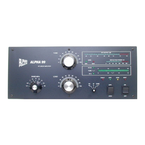
Page 25: Control Functions
Press OFF to remove primary AC power. OPR/STBY Operate places the amplifier in-line. With the 99 off, in STandBY, or in warm-up with the WAIT LED lighted, the amplifier is bypassed and the exciter is connected directly to the antenna. - Page 26 Grid Current The ALPHA 99 operates in Class AB2 when delivering maximum output power consistent with excellent linearity. A small amount of grid current flows and the green GRID MIN LED lights as drive approaches the optimum level. The green GRID LED will flicker on SSB voice peaks, and light under CW/SSTV/RTTY carrier conditions.
-
Page 27: Turning On The Amplifier
The 99 grid current limiting circuits provide substantial tube protection against possible damage. The ALC voltage generated by the 99 is for external feedback to transcievers. It cannot control the amplifier itself and is not applied internally. If ALC control is required, a connection must be made from the 99 to the transceiver ALC input. - Page 28 Radio Alpha Products Inc. ® Alpha 99...
-
Page 29: Table 1 – Preliminary Tuneup Settings
28.6 29.7 *Each Alpha 99 shipped from our factory will include an individual table showing the tune and load settings we used to achieve full output power on that amplifier into a 50 ohm delivery load. These settings may vary slightly from those in the manual. - Page 30 10. Repeat steps 6 and 7 at least twice. 11. Touch up TUNE for maximum power output. The ALPHA 99 is now correctly tuned to deliver 1500 watts RF output on SSB, CW, FSK, SSTV and FM. The TUNE LED normally fluctuates during modulation or keying.
-
Page 31: Tubes
Interlocks The ALPHA 99 is equipped with a cover interlock switch intended to remove primary power from the amplifier, and a crowbar to short-circuit the high voltage to chassis whenever the cover is lifted. -
Page 32: Fuses
Should the overcurrent relay trip, remove AC power from the amplifier, then determine and correct the cause of the trip before turning the 99 on again. Idling Plate Current And Electronic Bias Control (Ebs) Idling plate current of the ALPHA 99 is approximately 350 to 400 mA during fullpower transmission. - Page 33 Manual Alpha 99 Rev 1.doc...
-
Page 34: Preventive Maintenance
There are no user-accessible lubrication points in the amplifier. Do not apply oil or grease to any of the components. The exterior of the ALPHA 99 may be cleaned with a mild household liquid detergent such as Formula 409 or Fantastik. Do not use chemical solvents, as these may severely damage the front panel or cabinet finish. -
Page 35: Troubleshooting Hints
MHz as delivered within the US and possessions. As shipped to a US address, the amplifier is not operable on 21 MHz and above. Owners who send Alpha Power Customer Support a photocopy of their authorizing amateur license will promptly be provided information on “unlocking”... - Page 36 Amplifier turns on but time delay will not complete; WAIT LED does not turn off. Defect or damage in timing circuitry on control board. Amplifier turns on, time delay completes but amplifier will not transmit. Open T/R control line from transceiver to RELAY jack. Radio Alpha Products Inc. ® Alpha 99...
- Page 37 Excessive RF drive from transceiver and/or insufficient amplifier loading. Coaxial connector, coax feedline, antenna feedpoint balun, tuner, or antenna trap arcing on voice peaks. RF feedback from antenna into transceiver via the transceiver power cord, Radio Alpha Products Inc. ® Alpha 99...
- Page 38 In cases where objectionable hum is experienced while using the 99 and popular microphones such as the Heil series, the problem usually can be resolved by keeping the microphone at least 18 to 24 inches from the front of the amplifier and ensuring that transceiver mike gain, speech processing, and internal drive (ALC) levels are not adjusted to exceed 10 dB.
-
Page 39: Figure 6 – Simplified Chassis Schematic
Figure 6 – Simplified Chassis Schematic Radio Alpha Products Inc. ® Alpha 99... -
Page 40: Figure 7- Display Board Abx-X400
Figure 7- Display Board ABX-X400 Radio Alpha Products Inc. ® Alpha 99... -
Page 41: Figure 8 – Control Board Abx-X401
Figure 8 – Control Board ABX-X401 Radio Alpha Products Inc. ® Alpha 99... -
Page 42: Figure 9 – Control Board Abx-X401
Figure 9 – Control Board ABX-X401 Page 2 of 2 Radio Alpha Products Inc. ® Alpha 99... -
Page 43: Figure 10 – T/R Status Board, Multimeter Switch And Switch Matrix Board
Figure 10 – T/R Status Board, Multimeter Switch and Switch Matrix Board Radio Alpha Products Inc. ® Alpha 99... -
Page 44: Figure 11 – Power Supply Board
Figure 11 – Power Supply Board Radio Alpha Products Inc. ® Alpha 99... -
Page 45: Figure 12 – Hv Filter And Screen Supply Board
Figure 12 – HV Filter and Screen Supply Board Radio Alpha Products Inc. ® Alpha 99... -
Page 46: Figure 13 – T/R Status Board And Multimeter Switch
Figure 13 – T/R Status Board and Multimeter Switch Radio Alpha Products Inc. ® Alpha 99... -
Page 47: Figure 14 – Output Wattmeter Board
Figure 14 – Output Wattmeter Board Radio Alpha Products Inc. ® Alpha 99... -
Page 48: Figure 15 – Center Partition Board
Figure 15 – Center Partition Board Radio Alpha Products Inc. ® Alpha 99... -
Page 49: Figure 16 – Tube Deck Bcx-X413
Figure 16 – Tube Deck BCX-X413 Radio Alpha Products Inc. ® Alpha 99... -
Page 50: Figure 17 – Wiring Harness
Figure 17 – Wiring Harness Radio Alpha Products Inc. ® Alpha 99... -
Page 51: Alpha Products Warranty
ALPHA/POWER reserves the right to change its products as it deems desirable, without obligating itself to make such changes available for previously manufactured products. Radio Alpha Products Inc. ® Alpha 99... - Page 52 UNDER PROVISIONS OF THE FEDERAL MAGNUSON-MOSS WARRANTY ACT, THIS WARRANTY POLICY CLASSIFIED LIMITED WARRANTY. Radio Alpha Products Inc. ® Alpha 99...
- Page 53 Manual Alpha 99 Rev 1.doc...
Need help?
Do you have a question about the 99 and is the answer not in the manual?
Questions and answers