
Related Manuals for Steinbach Waterpower 5000


Summary of Contents for Steinbach Waterpower 5000
-
Page 1: User Manual
User manual speedheat speedheat Waterpower 5000 Art.Nr.: 00-49200 / BP-50HS-A speedheat speedheat Waterpower 8500 Art.Nr.: 00-49205 / BP-85HS-A... -
Page 3: Table Of Contents
Contents. General warnings and information for the addressee............5 1.1. Service Processing ........................5 1.2. Warranty..........................6 1.2.1. General conditions......................6 1.2.2. Special conditions......................6 1.2.3. Restrictions........................6 1.3. Symbol key...........................7 1.4. Safety regulations for heated pools..................7 1.5. - Page 4 6.2.1. Compressor and plate heat exchanger temperature sensors........21 6.2.2. High pressure sensor....................21 6.2.3. Low pressure sensor....................22 Routine, scheduled and extraordinary maintenance............23 7.1. User controls........................23 7.2. Specialised technician controls..................23 7.3.
-
Page 5: General Warnings And Information For The Addressee
Important note: On the pump label of your heat pump is a production number shown, please provide this number in the case of a complaint. Steinbach VertriebsgmbH, Aistingerstrasse 2, 4311 Schwertberg, AUSTRIA Tel. Austria: (0820) 200 100 111 (0,145€ per minute from all networks) Shott International S.r.l. -
Page 6: Warranty
1.2. Warranty. 1.2.1. General conditions. i. In accordance with these provisions, the dealer guarantees that the Product under this warranty (“the Product”) does not have any conformity defect upon delivery. ii. The Product Warranty Period is two (2) years, effective upon delivery to the purchaser. -
Page 7: Symbol Key
1.3. Symbol key. Indicates hazardous situations and warnings. The manual parts marked by this symbol must be read with the utmost care. Indicates that work must not be performed on live electrical equipment. This work can begin after taking safety measures. -
Page 8: Definitions
Failure to observe the instructions in this manual immediately null and voids the warranty. is not liable for any damages due to improper heat pump use. Steinbach VertriebsgmbH The manual must be kept integral and in good conditions. It must accompany the heat pump until it is decommissioned. -
Page 9: Composition
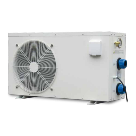
2.2. Composition. Fan protection net Body Display Refrigerant charge valve (inside for BP-35WS-B) Pressure manometer Water outlet Power cord Water inlet Heat exchanger Compressor Pressure sensor Heat exchanger Water sensor Four way valve Ambient sensor Plate heat exchanger temperature sensor Flow sensor... -
Page 10: Technical Specifications
3. Technical specifications. Model Unit of measure BP-35WS-B BP-50WS-B BP-50HS-A BP-85HS-A BP-100HS-A BP-160HS-A Thermal power (heating) [kW] 10.5 17.0 Refrigerant power (cooling) [kW] Absorbed power [kW] 0.75 Absorbed current 220-240 Power voltage [Hz] (Coefficient Of Performance) ERR (Energy Efficient Ratio) -
Page 11: Installation
If the heat pump is installed under the pool level, any water leaks could cause significant water leaks or floods. Steinbach VertriebsgmbH is not liable for any of said leaks, floods or consequent damages. -
Page 12: Necessary Clearance
4.3.2. Necessary clearance. Minimum clearance required for heat pump installation is illustrated in the following figure. Figure 2: Clearance required for correct installation. Clearance guarantees accessibility during SERIES BP heat pump maintenance and operations. -
Page 13: Electric/Electronic Waste Disposal
o The body and various parts, if unusable, should be dismantled and divided according to their material type (for example, copper, aluminium, plastic, etc.) and must be sent to collection centres. 4.4.3. Electric/electronic waste disposal. In keeping “Implementation of Directives 2002/95/CE, 2002/96/CE and 2003/108/CE”... -
Page 14: Electrical Connections
Working on live electrical equipment is prohibited. Before starting work, make sure the heat pump is disconnected from the electrical mains. Modifying electrical connections inside the heat pump without Steinbach VertriebsgmbH authorisation is strictly prohibited. Power voltage must not vary more than 10 % from the nominal value. It must be within the 207÷253 [V] interval. -
Page 15: Commissioning, Preliminary Checks
Figure 7: Protection device and/or contact switch. The electrical mains connected to the heat pump must be grounded. If a socket is installed for electrical mains connections, the latter must have a protection grade no lower than IPX4 and must have a grounding terminal. -
Page 16: Operations And Use
5. Operations and use. 5.1. Introduction. Please read the paragraph on energy savings, see Paragraph 1.5. SERIES BP heat pumps are equipped with control boards which, thanks to a simple but functional interface, allow heat pump programming to guarantee efficient service. Figure 8: Heat pump panel. -
Page 17: Starting The Heat Pump
5.2.4. Starting the heat pump. To start the heat pump, press . The heat pump starts within 3 minutes. The last selected operating mode (heating or cooling ), see Figure Figure 14 Paragraph 5.2.13.8, the last temperature set and the current pool water temperature (heating or cooling) is immediately displayed. -
Page 18: Automatic Start Settings
restart temperature are a –15 [° C] and –13 [° C] respectively, minimum admissible values. The minimum working temperature must be at least 2° C lower than the restart temperature. Proceed as follows to set minimum working temperature: When the pump is in standby, see Paragraph 5.2.2, press... -
Page 19: Manual Defrost
5.2.10. Manual defrost Frost may form on the plate heat exchanger during normal operations in heating mode, see Figure 1. Frost on the plate heat exchanger reduces heat pump performance. Frost is formed during heating mode because the heat pump cools surrounding ambient air to heat water. -
Page 20: Manometer Use
The temperature read by each sensor can be displayed by pressing (for model BP-xxWS-B (xx=35, 50), press and hold down for 3 seconds with the pump is running, see Paragraph 5.2.4. To display temperatures read by the various sensors, press (for model BP-xxWS-B (xx=35, 50), press ). -
Page 21: Control And Safety Devices
6. Control and safety devices. 6.1. Control devices. 6.1.1. Ambient and pool temperature sensors. SERIES BP control pumps are equipped with sensors that continuously check ambient and pool water temperatures. The sensors are located as illustrated in the following figures. -
Page 22: Low Pressure Sensor
Trigger pressure is 4.2 [bar]. After a high pressure alarm, see Paragraph 7.5, the heat pump must be manually restarted, see Paragraph 5.2.4. 6.2.3. Low pressure sensor. The low pressure sensor stops the compressor when suction pressure in the high pressure section is under the calibration value. -
Page 23: Routine, Scheduled And Extraordinary Maintenance
7. Routine, scheduled and extraordinary maintenance. Periodic controls are required to keep SERIES BP heat pumps in good working order and to guarantee the foreseen performance and safety levels. Some controls can be performed by the user while specialised technicians are required for others. - Page 24 turn off the heat pump, see Paragraph 5.2.3; turn on the heat pump, see Paragraph 5.2.1; start the heat pump, see Paragraph 5.2.4. Problem Possible cause solution solution The instructions in Follow the instructions in Paragraph 5.2.1 were not Paragraph 5.2.1...
- Page 25 Problem Possible cause solution solution Put the heat pump in Probable accumulation of standby, see Paragraph condensation. See 5.2.2, if the leak stops, this Paragraph 4.3. is normal condensation. Water leaks from the heat Possible water leak from pump.
- Page 26 Problem Possible cause solution solution The heat pump does not Compressor temperature Wait until compressor Contact specialised work and error message too high. temperature drops. technicians. EE 6 is displayed. The heat pump does not Contact specialised work and error message...
-
Page 27: Spare Parts
8. Spare parts. Nome file: 7500018 - ISTR.UTENTE HEAT PUMP VERS. EN.doc Rev. 6 del/of 12/04/2010 Speedheat Waterpower page 27 of 44 Page 27-di/of 32... - Page 28 Nome file: 7500018 - ISTR.UTENTE HEAT PUMP VERS. EN.doc Rev. 6 del/of 12/04/2010 Speedheat Waterpower page 28 of 44 Page 28-di/of 32...
- Page 29 Nome file: 7500018 - ISTR.UTENTE HEAT PUMP VERS. EN.doc Rev. 6 del/of 12/04/2010 Speedheat Waterpower page 29 of 44 Page 29-di/of 32...
- Page 30 XW35HSI001A XW50HSI018A XW50HSI001A XW100HSI001A XW100HSI018A XW160HSI001A XW35HSI017A XW35HSI002A XW35HSI002B XW50HSI017A XW50HSI002A XW100HSI002A XW100HSI017A XW160HSI017A XW160HSI002A XW160HSI002B XW50HSI008A XW50HSI003A XW85HSI008A XW50HSI003B XW100HSA008 XW160HSI008A XW50WSI004A XW50HSI004A XW50HSI019A XW50HSI005A XW50HSI020A XW100HSI005A XW160HSI005A XW35HSI006A XW50HSI006A XW100HSI006A XW160HSI006A XW35WSI007A XW50HSI007A...
- Page 31 XW35HSI044A XW50HSI033A XW50HSI044A XW85HSI033A XW85HSI044A XW100HSI033A XW100HSI044A XW160HSI033A XW160HSI044A XW35HSI045A XW50HSI034A XW50HSI045A XW85HSI034A XW100HSI034A XW100HSI045A XW160HSI034A XW160HSI045A XW35HSI035A XW50HSI046A XW50HSI035A XW160HSI046A XW160HSI048A XW100HSI035A XW160HSI049A XW160HSI035A XW160HSI050A XW35WSI036A XW160HSI051A XW50WSI036A XW50HSI036A XW85HSI036A XW100HSI036A XW160HSI036A XW35HSI037A XW50HSI037A...
- Page 32 Waterpower 5000 Art.Nr.: 00-49200 / BP-50HS-A speedheat speedheat Waterpower 8500 Art.Nr.: 00-49205 / BP-85HS-A Speedheat Waterpower page 32 of 44...
Need help?
Do you have a question about the Waterpower 5000 and is the answer not in the manual?
Questions and answers