Table of Contents
Advertisement
Quick Links
The All-Mode All-in-One Radio Interface
EZMaster
User's Guide
Version 01.05 – 04 Apr 2006
EZMaster
The
is manufactured in the EU
© Copyright 2003-2006 by HamRadioSolutions Co., Inc. All Rights Reserved.
EZMaster
Contents of this publication or the firmware within the
may not be reproduced in any form without the written permission of
the copyright owner.
Advertisement
Chapters
Table of Contents

Summary of Contents for HamRadioSolutions EZMaster
-
Page 1: Table Of Contents Version 01.05 - 04 Apr 2006
Version 01.05 – 04 Apr 2006 EZMaster is manufactured in the EU © Copyright 2003-2006 by HamRadioSolutions Co., Inc. All Rights Reserved. EZMaster Contents of this publication or the firmware within the may not be reproduced in any form without the written permission of... -
Page 2: Important Notice
Minor spelling corrections throughout the whole text. New Chapter: Quick Start Guide on page 21. Record here your EZMaster serial number (see page 6): ________________________________ Record here your EZMaster driver Virtual COM port (see page 19): __________________________ _____________________ Copyright Information CT™... -
Page 3: Radio Frequency Interference Statement
G round leads should be as short as possible and go to an EARTH GROUND • I nterconnecting cables appearing to act as radiators or antennas should be looped through a ferrite toroid. Be certain that toroids, when used, are designed for the frequency in use. EZMaster User’s Guide Page 3 of 53... -
Page 4: Table Of Contents
Configuring Your EZMaster ..............................19 Installing the EZMaster Driver ......................19 EZMaster Installer ..........................20 Quick Start Guide ................................21 A simple guide to setting up EZMaster ....................21 Logging Programs other than WinTest ....................21 Working with WinTest ........................22 EZMaster Quick Console..............................23 EZMaster Parameter’s FACTORY DEFAULT .........................25... - Page 5 PORT “A” RX............................ 34 PORT “A” TX............................ 34 PORT “B” RX............................ 35 PORT “B” TX............................ 35 Operating with Your EZMaster ..............................36 Voice Messages ...................................36 Programming Voice Messages ......................36 Playing back Messages ........................36 Aborting a Voice Message ......................... 36 Queuing Feature ..........................
-
Page 6: Introduction
References to the relevant questions that you may arise Major Uses of Your EZMaster By adding the EZMaster, and a computer, to your ham radio station, you will add a complete interface between your radios and the computer itself. This allows you to do the following: •... -
Page 7: Overview
EZMaster Overview EZMaster is a complete Device with a CMOS microprocessor and a non-volatile RAM chip for a full featured, all mode, multi-purpose interface. Ideal for DXers, Contesters, DXpeditioners and casual operators, brings a substantial reduction of the required amount of wiring and cabling while contributing to clean up the shack desk. -
Page 8: Features
In this mode inputs are accepted through the LPT Port, like the CW line, the A/B line, the PTT line, the DVP lines and the Band Map lines, or via the USB / RS232 Port like the CW/DTR line and PTT/RTS line. The Radios are connected to the EZMaster USB and/or RS232 ports that route to the Radio interface for Radio A and B. -
Page 9: So2R - Two-Radio Switching
EZMaster supports, in NORMAL and EXTENDED mode, the ability to control SO2R (Single Operator 2 Radio) functions with a single cable from the computer’s LPT port. The signal, from the logging program, that drives the Radio A / Radio B switch is fed to EZMaster which provides the relevant switching for the RX-audio, MIC-audio, CW-Out, FSK-Out, Digital-Out and PTTLine Out to the selected radio. -
Page 10: Radio Interface
RadioA / AmplifierA and RadioB / AmplifierB, through software configuration and these settings are retained in the EZMaster memory. This feature is available for all of the EZMaster’s PTT input control ways: Parallel Port, Serial Port, USB Port, Foot Switch, and Winkey. -
Page 11: Description
You probably have already understood it, but anyway here a description of how EZMaster operates, and how you can get it to work. EZMaster is a black box, not only due to its own colour, it does all the SO2R switching and related stuff: add a few cables and you are done, with a neat solution and a clean desk. -
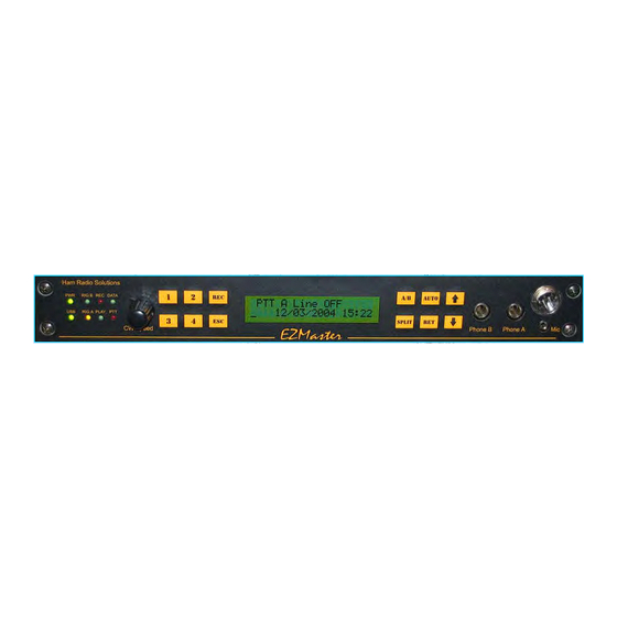
Page 12: The Center Keys And Display Section
RET key. The center back-lit LCD display section is the EZMaster window that shows a range of relevant informations. Mainly it shows, in real- time, the status of the device and the actual selection, along with the current DATE and TIME. -
Page 13: The Front Panel Keypad Menu
EZMaster You can easily locate the DIPswitch by removing the EZMaster box top panel. Unscrew the 4 screws on the box top to remove the top panel. Locate the DIPswitch in the front-right corner, just behind the front panel’s microphone connectors. -
Page 14: The Back Panel
Connector’s pinout section. Back panel Some examples of wiring are supplied later in this manual, (refer to the Wiring diagrams section) for some standard configurations. More can be found on the website at www.hamradiosolutions.com. EZMaster User’s Guide Page 14 of 53... -
Page 15: Installation
(i.e., connecting the parts) your radio station are as follows: connect your EZMaster to a power source and confirm that the unit powers on when it should, connect the “Computer” port on the EZMaster to a USB / Serial Port on your computer, install the EZMaster Control Console connect the “Radio(s)”... -
Page 16: Connecting Your Ezmaster To Your Computer
As illustrated before, there are two ways to supply power to your EZMaster: • You may use an external power supply by connecting the EZMaster to a 9-15V (13.8V nominal) DC source available on your bench. • You may use the USB port as a power source. -
Page 17: Connecting Ezmaster To Your Transceiver
The microphone input is on the front panel of the unit via a 3.5mm mono socket. The PTT footswitch signal is fed into an RCA connector at the back of EZMaster High quality shielded cable should be used for microphone and PTT/Footswitch leads. Use double- shielded cable for audio lines, if possible, to reduce chances of RFI. - Page 18 The RCA output connector for the Radio PTT is located on the unit’s back panel. Antenna Relay Control wiring The DB25 male connectors for Antenna Relay Control are located on the unit’s back panel. EZMaster User’s Guide Page 18 of 53...
-
Page 19: Configuring Your Ezmaster
Installing the EZMaster Driver The very first time that you will boot you PC with EZMaster connected through the USB port, the Operating System will acknowledge that a new USB peripheral has been connected and will start to look for the disk driver. Ensure that any existing virtual Comport software which provides COM ports via the USB connector of your computer is uninstalled from your computer BEFORE installing the EZMaster software for the USB port virtual Com port.Then please insert the CD-ROM shipped with your EZMaster or download the latest... -
Page 20: Ezmaster Installer
Install I/O Port This selection is needed only if you want to test your EZMaster Parallel Port function with the EZManager and you are using a Win2K or WinXP operating system. The installed I/O driver will allow the direct access to each pin of the parallel port, while allowing most of the applications to workaround the Win2K and WinXP direct access blocking;... -
Page 21: Quick Start Guide
Note that for transceiver CAT connections, where the manual says “Radio TX” it should be connected to the line on the radio marked “serial in” or similar. In other words the EZMaster line shown as data TX goes to the data receiving pin on the radio. Note also that for transceivers such as the FT1000MP with a built in RS232 interface, the pins on EZMaster for serial communication are different from those shown in the manual. -
Page 22: Working With Wintest
If you have completed the above successfully, you can now explore the more advanced functionality of EZMaster. The next sections of this Manual set out in greater detail some of the set-up process for EZMaster, and inevitably repeat some of the information in the “Quick Start”... -
Page 23: Ezmaster Quick Console
WRITELOG, N1MMLogger, along with two free slots for general-purpose application, either DOS or Windows, are available. Select the Comport number corresponding to the Virtual Serial Port where EZMaster is connected, on your computer, and then click on the “OFF LINE” button. If the selected connections are properly working it should toggle into “ON LINE” and you will see the EZMaster and Winkey Version numbers displayed in the corresponding textboxes. - Page 24 When finished, press the CONFIGURE Green Button to transfer the configuration information to EZMaster. These information are saved into an internal memory. You will see some acknowledgement of the commands sent to EZMaster – the LCD window on EZMaster will report a status change.
-
Page 25: Ezmaster Parameter's Factory Default
EZMaster EZMaster Parameter’s FACTORY DEFAULT Parameter Default Value General Parameters Operating Mode Extended CW Port Parallel & USB Parallel PTT Enabled Parallel Radio A/B Enabled Parallel DVK Enabled Parallel Band Data Enabled Parallel Band Data Decoder Enabled Communication Routing Radio A... -
Page 26: Ezmanager
DOS, Windows or Linux. The Advanced mode is the next generation interface that allows a full control of EZMaster only via one single USB port. Few developers, at the time of writing these notes, are evaluating to support EZMaster in this mode with the exception of Wintest.. -
Page 27: Standard Tab
Logging / Contest application. In this panel you can verify the correct connection between PC and EZMaster, and so it is also a powerful troubleshooting tool. The parallel connection has a lot of information on it: CW out, PTT out, RADIO A/B selector, Antenna Relays Switch output and the Voice Keyer output. - Page 28 EZMaster Parallel frame By checking the PTT checkbox EZMaster will close the corresponding Output Relay, PTT A or PTT B, according to the RADIO A/B checkbox RADIO A/B Clicking on the RADIO A/B checkbox the related radio is selected accordingly. All the signals PTT, Digital Voice Keyer, Speaker Keyer and Microphone are routed to the selected radio.
-
Page 29: Extended Tab
TX status. Grayed out commands, including Profiles, can be sent to EZMaster only after checking the “Setting” radio button in the Command frame. “SETTING MODE” will be shown on the EZMaster Display, and gray buttons will become available. After setting your configuration select the “Run”... -
Page 30: Advanced Tab
Advanced TAB The advanced TAB shows all the EZManager advanced commands. In this mode the communication between PC and EZMaster is done via the USB port, or via the COM port for those operating systems that don’t support a USB device ( DOS ). - Page 31 Some devices, such as Step by Step relays, need only a pulse command to excite the coil and for this purpose, by enabling the Pulse A / Pulse B check box, EZMaster will output only a pulse at the corresponding Matrix A/B output connector.
- Page 32 Clicking on the “OFF” button, that should toggle into “ON”, enables the Winkey built-in keyer (www.k1el.com). The Version and pot speed is then shown to indicate that the initialization has been properly done. The Paddle Keyer input of EZMaster is switched to Winkey, when it is enabled.
- Page 33 Play/send the 7en message, both SSB or CW. ( Band Map Profile frame The Band Map profile is one of the highlight functions of EZMaster. It allows you to define which output line of the MATRIX DB25 connector will close and, consequently, which connected Relay, or any other supported device, i.e.
-
Page 34: Advanced Mode Profiling
(ON/OFF) the corresponding line. In particular, one of the big differences between EZMaster and other standard Parallel Antenna Matrix Output is that you can directly select any output without the need of any additional external wired diode for a matrix antenna/filter switch configuration. -
Page 35: Port "B" Rx
EZMaster ANTENNA MATRIX PORT “B” RX Configuration ANTENNA MATRIX PORT “B” TX Configuration EZMaster User’s Guide Page 35 of 53... -
Page 36: Operating With Your Ezmaster
NA uses pin 7 & 8 of the LPT to switch between radios while TRLog, CT, N1MM and WriteLog uses pin 14. EZMaster can be configured through software to use pin 14 of the LPT to switch between radios, or 7 & 8. -
Page 37: Cw And Ptt
AUTO (fully Computer/Logging program Controlled) In AUTO mode EZMaster puts both ears on the “inactive” radio when a DVK or CW message is called for or sent from the logging program. A user defined delay time can be added before switching ears to the inactive radio, allowing a short monitor of the beginning of the transmission on the active radio. -
Page 38: Connector's Pinout
OUT #7 OUT MATRIX A #11 OUT #8 OUT MATRIX A #12 OUT #9 OUT MATRIX A #13 OUT #10 OUT MATRIX A #14 OUT MATRIX A #15 OUT MATRIX A #16 +VCC EZMaster User’s Guide Page 38 of 53... -
Page 39: Com Port
EZMaster COM Port Description RS232 Port Description Aux Port Description Keypad port Description CLOCK RESET DATA DATA AKNOWLEDGE EZMaster User’s Guide Page 39 of 53... -
Page 40: Rtty Port
Note: For ICOM radio cables Pin 4 and 5 must be connected together Microphone Port Description PTT OUT PTT GND MIC LINE MIC LINE GND SPEAKER port Description AUDIO OUT LEFT AUDIO OUT RIGHT AUDIO GND EZMaster User’s Guide Page 40 of 53... -
Page 41: Wiring Diagrams
In this chapter we refer to a few samples of the wiring diagrams you may find useful to accomplish your set-up. More wiring diagrams can be found, and downloaded, in the Download Manuals section of the web site at www.hamradiosolutions.com. -
Page 42: Ct_Dos So2R Wiring
Radio A Radio B Front Panel Front Panel Phone Phone Radio A Radio B Back Panel Back Panel RTTY CW Key RTTY CW Key FootSwitch Parallel RS232 RS232 Computer KEYER CT_DOS SO2R wiring (SSB/CW) EZMaster User’s Guide Page 42 of 53... -
Page 43: Writelog So2R Wiring
Radio B Front Panel Front Panel Phone Phone Radio A Radio B KeyPad Back Panel Back Panel RTTY CW Key RTTY CW Key FootSwitch Parallel RS232 RS232 Computer KEYER WRITELOG SO2R wiring (SSB/CW) EZMaster User’s Guide Page 43 of 53... -
Page 44: N1Mm So2R Wiring With Usb
Phone Radio A Radio B KeyPad Back Panel Back Panel RTTY CW Key RTTY CW Key FootSwitch Parallel RS232 RS232 RS232 Computer Audio OUT Audio IN KEYER N1MM SO2R wiring (SSB/CW) using USB EZMaster User’s Guide Page 44 of 53... -
Page 45: Mixw So1R Wiring With Usb For Fsk
EZMaster MixW SO1R wiring with USB for FSK Amplifier Radio A Radio A Front Panel Phone Radio A Back Panel RTTY CW Key RS232 Computer MixW SO1R wiring (FSK) EZMaster User’s Guide Page 45 of 53... -
Page 46: Theory Of Operation
EZMaster Block Diagram The Block Diagram shows the main features of EZMaster: an 8 bit CPU Processor managing the data flow from 6 serial ports, and several external devices. Data received from the USB, COM and LPT Port or the external keypad, are processed and executed in parallel tasks, driving the requested function, as DVK Processor, Winkey, Radio Interface, PTT/PTTDelayed line, CW interface, FSK interface, A/B line and the Antenna Matrix Data Processor. -
Page 47: Standard Mode
0 or 1 levels. In Standard Mode, EZMaster follows the previous table settings for the pin out of the ANTENNA MATRIX A DB25 Connector. In this mode there is a direct relationship between the Parallel and the decoded ANTENNA MATRIX A output. -
Page 48: Extended Mode
The Extended mode enables also a smart way to manage the Voice Keyer messages through the Parallel Port. As shown in the table below, all the 16 combinations of the 4 pin of the parallel port are recognized, so all the seven EZMaster messages can be played and recorded including also a STOP command for both function. -
Page 49: Extended Band Data Profile
Play # 2 Play # 5 Play # 6 Play #7 Play # 1 Rec # 4 Rec # 3 Rec # 1 Rec # 2 Rec # 5 Rec # 6 Stop EZMaster User’s Guide Page 49 of 53... -
Page 50: Advanced Mode
Moreover the Advanced Mode can be used in combination with the Parallel (LPT) port control. This unique feature allows a total control over the EZMaster itself, giving the user the maximum flexibility like having the CW keying through the parallel port and the other functions through EZMaster command set protocol. -
Page 51: Hardware Specifications
The three sound card audio signals are isolated using three audio transformers. The Radio PTT output signals are isolated using, DPDT relays. CW and FSK Output are opto-isolated. The relays provide adequate current and voltage capability to switch tube rigs. EZMaster User’s Guide Page 51 of 53... -
Page 52: Mainboard Printed Circuit (Rev.4.00)
EZMaster Mainboard Printed Circuit (Rev.4.00) EZMaster User’s Guide Page 52 of 53... -
Page 53: Ezmaster User's Guide
EZMaster Take your Personal Notes here EZMaster User’s Guide Page 53 of 53... - Page 54 Version 01.01 – 28/07/2004 EZMaster is manufactured in the EU © Copyright 2003-2004 by HamRadioSolutions Co., Inc. All Rights Reserved. Contents of this publication or the firmware within the EZMaster may not be reproduced in any form without the written permission of...
- Page 55 In this document we have collected a few samples of the wiring diagrams you may find useful to accomplish your set-up. More wiring diagrams are possible and you can design your own with the help of the documentation of both EZMaster and your contest logging program.
-
Page 56: N1Mm So1R Wiring With Usb
EZMaster N1MM SO1R wiring with USB Amplifier Radio A Radio A Front Panel Phone Radio A KeyPad Back Panel RTTY CW Key FootSwitch Parallel RS232 Computer KEYER N1MM SO1R wiring (SSB/CW) using USB N1MM – wiring... -
Page 57: N1Mm So1R Wiring Using A Com Port And A Band Switch
EZMaster a COM port and a Band Switch N1MM SO1R wiring using Amplifier Radio A Radio A Front Panel Phone Radio A KeyPad Back Panel RTTY CW Key FootSwitch Parallel RS232 Computer KEYER N1MM SO1R wiring (SSB/CW) using a COM port and a Band Switch... -
Page 58: N1Mm So2R Wiring Using Com Ports
EZMaster N1MM SO2R wiring using COM ports Amplifier Radio A Amplifier Radio B Radio A Radio B Front Panel Front Panel Phone Phone Radio A Radio B KeyPad Back Panel Back Panel RTTY CW Key RTTY CW Key FootSwitch Parallel... -
Page 59: N1Mm So2R Wiring With Usb And Band Switches
EZMaster N1MM SO2R wiring with USB and Band Switches Amplifier Radio A Amplifier Radio B Radio A Radio B Front Panel Front Panel Phone Phone Radio A Radio B KeyPad Back Panel Back Panel RTTY CW Key RTTY CW Key... - Page 60 EZMaster configuration Table for N1MM Logger Radio Mode USB RADIO COM RADIO 232 RADIO USB PTT COM PTT AUX PTT LPT PTT USB CW COM CW AUX CW USB FSK COM FSK AUX FSK LPT DVK/CW SSB/CW ● ● ●...
- Page 61 Version 01.01 – 03/04/2006 EZMaster is manufactured in the EU © Copyright 2003-2006 by HamRadioSolutions Co., Inc. All Rights Reserved. Contents of this publication or the firmware within the EZMaster may not be reproduced in any form without the written permission of...
- Page 62 The purpose of this Technical Bulletin is to provide news, hints, and all sorts of information that may give users a better knowledge of the usage, configuration and capability of EZMaster. This kind of information should be regarded as extension to the EZMaster User Guide. The Technical Bulletin will be published as needed and will not be a periodical publication.
- Page 63 After having selected the right value press RET to exit from this menu. The CAT Delay is then saved into EZMaster and there is no need to set it again, unless you may need to change it for other reasons.
- Page 64 Version 01.01 – 28/07/2004 EZMaster is manufactured in the EU © Copyright 2003-2004 by HamRadioSolutions Co., Inc. All Rights Reserved. Contents of this publication or the firmware within the EZMaster may not be reproduced in any form without the written permission of...
- Page 65 In this document we have collected a few samples of the wiring diagrams you may find useful to accomplish your set-up. More wiring diagrams are possible and you can design your own with the help of the documentation of both EZMaster and your contest logging program.
-
Page 66: Writelog So1R Wiring With Usb
EZMaster WRITELOG SO1R wiring with USB Amplifier Radio A Radio A Front Panel Phone Radio A KeyPad Back Panel RTTY CW Key FootSwitch Parallel RS232 Computer KEYER WRITELOG SO1R wiring (SSB/CW) using USB WRITELOG wiring... -
Page 67: Writelog So1R Wiring Using A Com Port And A Band Switch
EZMaster WRITELOG SO1R wiring using a COM port and a Band Switch Amplifier Radio A Radio A Front Panel Phone Radio A KeyPad Back Panel RTTY CW Key FootSwitch Parallel RS232 Computer KEYER WRITELOG SO1R wiring (SSB/CW) using a COM port and a Band Switch... -
Page 68: Writelog So2R Wiring Using Com Ports
EZMaster WRITELOG SO2R wiring using COM ports Amplifier Radio A Amplifier Radio B Radio A Radio B Front Panel Front Panel Phone Phone Radio A Radio B KeyPad Back Panel Back Panel RTTY CW Key RTTY CW Key FootSwitch Parallel... -
Page 69: Writelog So2R Wiring With Usb And Band Switches
EZMaster WRITELOG SO2R wiring with USB and Band Switches Amplifier Radio A Amplifier Radio B Radio A Radio B Front Panel Front Panel Phone Phone Radio A Radio B KeyPad Back Panel Back Panel RTTY CW Key RTTY CW Key... - Page 70 EZMaster configuration Table for WRITELOG for Windows™ Radio Mode USB RADIO COM RADIO 232 RADIO USB PTT COM PTT AUX PTT LPT PTT USB CW COM CW AUX CW USB FSK COM FSK AUX FSK LPT DVK/CW ● ● ●...
- Page 71 EZMaster wiring combination with most popular Logging Software Program Radio Mode USB RADIO COM RADIO 232 RADIO USB PTT COM PTT AUX PTT LPT PTT USB CW COM CW AUX CW USB FSK COM FSK AUX FSK LPT DVK/CW CT_DOS ●...
- Page 72 Microphone Cable ICOM EzMaster Back Panel View IcomMic EZMaster Cable Lenght 90 cm...
- Page 73 Microphone Cable YAESU EzMaster Back Panel View YaesuMic EZMaster Cable Lenght 90 cm...
- Page 74 Microphone Cable Kenwood EzMaster Back Panel View Kenwood Mic EZMaster Cable Lenght 90 cm...
- Page 75 Microphone Cable Orion EzMaster Back Panel View Orion Mic EZMaster Cable Lenght 90 cm...
- Page 76 Speaker Connector Jack Audio 6.3 EzMaster Back Panel View Jack 6.3 EZMaster Left Right Ground Cable Shield 6 Cable Length 90 cm...
- Page 77 Serial Cable ( COM ) DB9 Male / Female DB9 Male DB9 Female Cable Length 200 cm Serial Cable ( AUX ) EzMaster Back Panel View MiniDin 6 DB9 Female Cable Length 200 cm...
- Page 78 CW Cable RCA Connector Jack 6.3 Cable Lenght 150 cm...
- Page 79 ICOM CI-V Cable Minidin & Jack 3.5 Cable Length 90 cm Jack 3.5 EzMaster Back Panel View Jack 3.5” MiniDin Ground Cable Shield Tip and Ground need to be connected together...
- Page 80 Radio KENWOOD Cable MiniDin 6, DIN 6 Cable Length 90 cm EzMaster Back Panel View DIN 6 MiniDin 6 4 connected to 5 DIN 5 connected to 4 DIN...
- Page 81 Radio YAESU Cable MiniDin 6, DIN 6 Cable Length 90 cm EzMaster Back Panel View DIN 6 MiniDin 6...
- Page 82 RTTY / FSK / AFSK ICOM Cable MiniDin 8, DIN 8 Cable Length 150 cm EzMaster Back Panel View DIN 8 MiniDin 8...
- Page 83 RTTY / FSK / AFSK FT1000 Mark V Cable MiniDin 8, DIN 4 Cable Length 150 cm EzMaster Back Panel View DIN 4 MiniDin8...
- Page 84 RTTY / FSK / AFSK Kenwood Cable MiniDin 8 , DIN 13 Cable Length 150 cm EzMaster Back Panel View DIN 13 Minidin8...
- Page 85 RTTY / FSK / AFSK ORION Cable MiniDin 8 , DIN 8 Cable Length 150 cm DIN 8 MiniDin 8 4(6)
Need help?
Do you have a question about the EZMaster and is the answer not in the manual?
Questions and answers