Advertisement
TRADESMAN
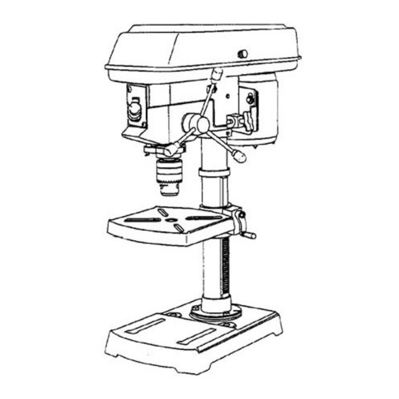
12" DRILL PRESS WITH LASER GUIDE
Model # DP12LW
Item #52759
CAUTION – FOR YOUR OWN SAFETY
READ YOUR OWNER'S MANUAL THROUGH COMPLETELY AND CAREFULLY BEFORE
ATTEMPTING TO SET-UP OR OPERATE YOUR NEW POWER TOOL.
ALL OPERATORS OF THIS EQUIPMENT SHOULD READ AND UNDERSTAND ALL SAFETY
RULES PRINTED ON THE MACHINE AND THIS OWNERS MANUAL BEFORE USE.
Your new Power Tool is a well built, carefully inspected versatile machine, capable of giving
you many years of dependable service. Your power tool comes complete in one carton with
a minimum of first assembly and setup required by you. When unpacking , be sure to check
all packages and packing material for loose parts before discarding.
NOTICE: On the nameplate of your machine you will find the serial number and MFG date code of
your unit. Please record these numbers on this manual cover for future service reference.
SERIAL #
POWER TOOL SPECIALISTS, INC E.WINDSOR,CT 06088 PRINTED IN CHINA
MFG. DATE #
www.tradesman-rexon.com
1-800-243-5114
PURCHASE DATE:
®
.
Advertisement
Table of Contents

Related Manuals for Tradesman DP12LW

Summary of Contents for Tradesman DP12LW
- Page 1 TRADESMAN ® 12” DRILL PRESS WITH LASER GUIDE Model # DP12LW Item #52759 CAUTION – FOR YOUR OWN SAFETY READ YOUR OWNER’S MANUAL THROUGH COMPLETELY AND CAREFULLY BEFORE ATTEMPTING TO SET-UP OR OPERATE YOUR NEW POWER TOOL. ALL OPERATORS OF THIS EQUIPMENT SHOULD READ AND UNDERSTAND ALL SAFETY RULES PRINTED ON THE MACHINE AND THIS OWNERS MANUAL BEFORE USE.
-
Page 2: Table Of Contents
TABLE OF CONTENTS PAGE SECTION PAGE SECTION Product Specifications …………………….. Know Your Drill Press ……...…….……… Power Tool Safety ..……………………….. Drill Press Glossary ………………………. Drill Press Safety ………………………..… Assembly …………………………………. Electrical Requirements and Safety……….. Adjustments……………………..………… Accessories and Attachments……………… Operation…………………………………. Tools Required For Assembly…………..Maintenance ………………………………... -
Page 3: Power Tool Safety
POWER TOOL SAFETY 13. USE RECOMMENDED ACCESSORIES. Consult the BEFORE USING THIS DRILL PRESS owner’s manual for recommend accessories. The use of Safety is a combination of common sense, staying alert and improper accessories may cause risk of injury to persons. knowing how to use your drill press. - Page 4 DRILL PRESS SAFETY CAUTION! 14. SECURE THE WORK. Use clamps or a vise to hold the work when practical. It’s safer than using your hand and it For your own safety, do not try to use your drill press or plug it frees both hands to operate tool.
-
Page 5: Grounding Instructions
ELECTRICAL REQUIREMENTS AND SAFETY GROUNDING INSTRUCTIONS This tool is intended for use on a circuit that has a receptacle like the one illustrated in FIGURE A. IN THE EVENT OF A MALFUNCTION OR FIGURE A shows a 3-prong electrical plug and receptacle that BREAKDOWN, grounding provides a path of least resistance has a grounding conductor. -
Page 6: Accessories And Attachments
PRE ASSEMBLY ACCESSORIES AND ATTACHMENTS CARTON CONTENTS Use only the recommended accessories with this drill press. UNPACKING AND CHECKING CONTENTS Follow the instructions that are supplied with these accessories. CAUTION! If any part is missing or damaged, do not plug the drill press in CAUTION! until the missing or damaged part is replaced, and assembly is Use of improper accessories may cause hazards. - Page 7 CARTON CONTENTS...
-
Page 8: Know Your Drill Press
KNOW YOUR DRILL PRESS Spindle Motor pulley pulley Depth scale Depth Scale stop nuts point Cord clamp Depth scale Belt Feed stop rod tension Spring Cover knob Head locking Feed spring Depth stop screw Spindle Column collar Bevel scale ON/OFF Table support switch w/key Motor... -
Page 9: Drill Press Glossary
DRILL PRESS GLOSSARY DRILL ON/OFF SWITCH – Has a locking feature. This BASE – Supports drill press. For additional stability, holes are feature is intended to help prevent unauthorized and provided in base to bolt drill press to floor. possible hazardous use by children and others. Insert the key (See “Specific Safety Instructions for Drill Presses”) into the switch to turn the drill press on. -
Page 10: Assembly
ASSEMBLY Estimated Assembly Time 20~40 minutes Fig. 3 CAUTION! The drill Press is very heavy and must be lifted with the help of 2 PEOPLE OR MORE, to safely assemble it. COLUMN SUPPORT TO BASE (FIG. 1) 1. Position the base (1) on the floor. 2. - Page 11 ASSEMBLY INSTALLING FEED HANDLES (FIG. 8) Fig. 5 1. Locate three feed handles in the loose parts bag. 2. Screw the feed handles (1) into the threaded holes (2) in the hub (3). Tighten. Fig. 8 8. Install the table crank handle (9) to the worm gear shaft (1) on the side of the table support (3 –...
- Page 12 ASSEMBLY Unlock the table support lock (4 – Fig. 4) and swing the table away from the bottom of the chuck. Lock the table support lock. Using a mallet or a hammer and a block of wood, tap the chuck up firmly (Fig. 11). Fig.
-
Page 13: Adjustments
ADJUSTMENTS SPINDLE / QUILL (FIG. 13) Fig. 14 Rotate the feed handles counterclockwise to lower spindle to its lowest position. Hand support the spindle securely and move it back and forth around the axis. If there is too much play, do the following: 1. - Page 14 ADJUSTMENTS THE LASERGUIDE ADJUSTING THE LASER LINES ( Fig. 16) Your tool is equipped a battery powered Laser Guide using The Laser beam must always be correctly aligned with the Class II laser beams. The laser beams will enable you to bit.
-
Page 15: Operation
OPERATION SPEEDS AND BELT PLACEMENT (FIG. 17 CAUTION! This drill press has 12 speeds, as listed below: ALWAYS lock the switch “OFF” when the drill press is not 250 RPM 600 RPM 1620 RPM in use. Remove the key and keep it in a safe place. In the 340 RPM 650 RPM 1900 RPM... - Page 16 OPERATION 4. The drill bit will stop after traveling the distance selected CAUTION! on the depth scale. To prevent the workpiece or backup material from being torn from your hands while drilling, you MUST position the Fig. 21 workpiece against the LEFT side of the column. If the workpiece or the backup material is not long enough to reach the column, clamp them to the table, or use a vise to brace the workpiece.
- Page 17 OPERATION i. Use fixtures for unusual operations to adequately BASIC OPERATION INSTRUCTIONS hold, guide, and position workpiece. To get the best results and minimize the likelihood of j. Use the Drilling Speed Table for the specific personal injury, follow these instructions for operating your operation of workpiece material.
- Page 18 OPERATION POSITIONING THE TABLE AND WORKPIECE HOLDING A DRILLING LOCATION IN METAL (FIG. 23, 24) 1. Using a centerpunch, make an indentation in the 1. Lock the table (1) to the column (2) at a position so the workpiece where you want the hole. tip of the drill bit (3) is just above the top of the 2.
-
Page 19: Maintenance
MAINTENANCE CAUTION! CHANGING THE LASER GUIDE BATTERIES (FIG. 26) Unplug your drill press. For your own safety, turn the switch OFF and remove the plug CAUTION! from the power source outlet before maintaining or lubricating your drill press. Failure to unplug your tool could result in accidental starting causing possible serious personal injury. -
Page 20: Troubleshooting Guide
TROUBLESHOOTING TROUBLESHOOTING GUIDE CAUTION! To avoid injury from an accidental start, turn the switch “OFF” and always remove the plug from the power source before making any adjustment. Consult your local your Service Center if for any reason the motor will not run. PROBLEM POSSIBLE CAUSES REMEDY... - Page 21 PART LIST I.D. Description Size I.D. Description Size 2935 WARNING LABEL 0JTA HEX. HD. BOLT 1/2*12UNC-7/8 2937 WARNING LABEL 0JXE HEX. SOC. SET SCREW M8*1.25-8 2938 LABEL 0JXE HEX. SOC. SET SCREW M8*1.25-8 2939 TRADE-MARK LABEL 0K7K CR. RE. ROUND WASHER HD. SCREW M6*1.0-12 047X POINTER...
Need help?
Do you have a question about the DP12LW and is the answer not in the manual?
Questions and answers