Table of Contents
Advertisement
Advertisement
Table of Contents

Related Manuals for Platinum CCTV DVR-2649S

Summary of Contents for Platinum CCTV DVR-2649S
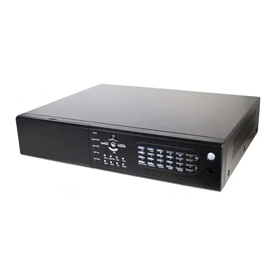
- Page 1 DVR-2649S 9-Channel H.264 Standalone DVR User’s Manual http://Platinum-CCTV.com With IR Remote Control & USB Backup (All Models) With Network Remote Viewing (All Models) Please read instructions completely before operation and retain manual for future reference Platinum-CCTV DVR v1.0...
- Page 2 CAUTION TO REDUCE THE RISK OF ELECTRIC SHOCK, DO NOT REMOVE COVER. NO USER SERVICEABLE PARTS INSIDE. PLEASE REFER SERVICING TO QUALIFIED SERVICE PERSONNEL. WARNING TO PREVENT FIRE OR ELECTRIC SHOCK HAZARD, DO NOT EXPOSE THIS APPLIANCE TO RAIN OR MOISTURE. NOTE: This equipment has been tested and found to comply with the limits for a Class “A”...
-
Page 3: Limitation Of Liability
LIMITATION OF LIABILITY THIS PUBLICATION IS PROVIDED “AS IS” WITHOUT WARRANTY OF ANY KIND, EITHER EXPRESS OR IMPLIED, INCLUDING BUT NOT LIMITED TO, THE IMPLIED WARRANTIES OF MERCHANTIBILITY, FITNESS FOR ANY PARTICULAR PURPOSE, OR NON-INFRINGEMENT OF THE THIRD PARTY’S RIGHT. THIS PUBLICATION COULD INCLUDE TECHNICAL INACCURACIES OR TYPOGRAPHICAL ERRORS. - Page 4 PRECAUTIONS Please refer all work related to the installation of this product to qualified service personnel or system installers. Do not operate the appliance beyond its specified temperature, humidity or power source ratings. Use the appliance at temperatures between 0 C ~ +45 C (32 F ~ 113...
-
Page 5: Table Of Contents
Table of Contents 1. Product Overview………………….……………………….……... 1.1 Features…………………..…….…………..…………………... 2. Panels And Remote Controller…………...………………….……. 2.1 Front Panel………….……….…………………………….……. 2.2 Back Panel………………….…………………………….…….. 2.3 Remote Controller…………..…….……………………….…… 3. Installations…….…….……………………………………….…… 3.1 Basic Connections…………….………………………….…….. 3.2 Optional Connections…………..………………………….…… 4. Main Screen And Basic Operations………….……..……….…... 4.1 Text Input……………………………………….……………… 4.2 Login And Logout……………………………………………… 4.3 Basic Operations…………………………….…………………... - Page 6 6.10.2 Advanced Network Setup……………..………………… 7. PTZ Control……………………….……………………………… 8. Search/Playback/Archive (Administrator/Supervisor) ………..8.1 Search By Time……………………………………….………… 8.2 Search By Event / Log Display………………………….……… 8.3 Search Archived Files………………………….……….……… 8.4 Playback/Archive For Search By Time………….….….……… 8.5 Playback/Archive For Search By Event………………………… 8.6 Playback For Archived Files…………………………………… 9.
-
Page 7: Product Overview
1. Product Overview The H.264 digital video/audio recorders are designed for use within a surveillance system and are a combination of a hard disk recorder, a video multiplexer, and a web server. To achieve the highest inter-connectivity and inter-operability, this series of digital video/audio recorders are all based on industry-leading front-end to back-end surveillance infrastructure. -
Page 8: Panels And Remote Controller
2. Panels and Remote Controller 2.1 Front Panel 1. Front Door Conceal Hard Disk Tray (and internal DVD for DVD models). For internal DVD, please open the front door in order not to block the tray from ejecting, esp. while it’s in backup process. - Page 9 8. SEARCH Button Press this button to display the search menu in main screen display. In some dialogs, this button is used as a miscellaneous function key. 9. CALL Button Press this button to switch to or return from full screen display of the focus camera in main screen display.
- Page 10 20. Down/DEL Button (▼/DEL) Press this button to move the cursor or focus window in most circumstances. In PTZ control, press this button to tilt down the camera. In text editing mode, this button is used as “del” key. 21. Fast Backward Button ( Press this button for fast backward playback.
-
Page 11: Back Panel
2.2 Back Panel 1. Video Input Connectors (1-16/1-9) Connect system cameras to these BNC connectors. The corresponding 75Ω termination (see # 5) must be made unless the video output terminal is connected. 2. Video Output Connectors (1-16/1-9) Connect these BNC connectors for looping the corresponding camera video inputs. 3. - Page 12 10. RS-232 Connector Connect this connector to PTZ camera(s). 11. RS-422/485 Selector Switch Used to select RS-422/485 3-line or 2-line. 12. RS-422/485 Connector Connect this connector to RS-422/485 compatible PTZ camera(s) or keyboard. Please set the Selector Switch correctly. Please refer to the manuals that come with the RS-422/485 compatible devices for the correct settings.
-
Page 13: Remote Controller
2.3 Remote Controller The remote controller is an optional accessory to ease the user’s operations. You can do all the operations by the remote controller instead of the buttons on the front panel. The effective distance is about 10 meters without any obstacle. DVR ID selection buttons 1. -
Page 14: Installations
3. Installations The installations described below should be made by qualified service personnel or system installers. 3.1 Basic Connections Please refer to the following diagram for the connections. Please make sure to set the NTSC/PAL Selector Switch on the back panel according to the local TV system for the digital video/audio recorder to work correctly. -
Page 15: Optional Connections
Before connection After connection Power Plug 115 VAC or 230 VAC power source into the power socket. 3.2 Optional Connections Audio inputs Connect the audio input connectors to the audio line-outs from system cameras or other audio sources. Please make sure to associate the audio inputs with the cameras in Camera Setup as described in Section 6.2 accordingly. - Page 16 USB 2.0 disk drives, DVD+RW, card reader, etc. If the user wants to use USB2.0 peripheral device to retrieve important recorded images and/or audio, please connect it to the USB port connectors (one on the front panel, the other on the back panel). I/R remote controller If there are more than one digital video/audio recorders to be controlled by the I/R remote controller, please set the DVR ID on the front panel.
- Page 17 Set this unit to 3-line or 2-line according to the connected devices. For 4-line devices (such as keyboard) Devices TxD- TxD- TxD+ TxD+ RxD- RxD- RxD+ RxD+ For PTZ cameras Devices TxD- RS485- TxD+ RS485+ RxD- RxD+ MAIN-AUX monitor Please refer to the diagram below to connect the MAIN-AUX monitor output connector to a surveillance TV monitor or the MAIN-AUX monitor input connector of another digital video/audio recorder.
- Page 18 CALL-AUX monitor Please refer to the diagram below to connect the CALL-AUX monitor output connector to a surveillance TV monitor or the CALL-AUX monitor input connector of another digital video/audio recorder. The CALL-AUX monitor, if enabled, has the same output display as the call monitor, and is typically used with RS-485 keyboard controller for distant monitoring and control (e.g.
-
Page 19: Main Screen And Basic Operations
4. Main Screen And Basic Operations The split-window screen, as shown above, is the main screen after system startup. There are several types of split-window screens, including 1-Window, 4-Window, 7-Window, 9-Window, 10-Window, 13-Window, and 16-Window. The system will remember the last one before normal shutdown (as described in Section 5.7) of the system. -
Page 20: Login And Logout
(3) Press code in text editing mode to change text case. (If this entry can accept number only, pressing code will have no effects.) Indicators on the screen show the current setting: 123 = Number only abc = No capital letters ABC = All capital letters CODE = Internal code for the selected language, such as Chinese, Japanese, etc. -
Page 21: Basic Operations
There is one factory-preset login name/password aa/11 at Administrator level. The user can use it to login the system for the first time. Should the user have forgotten all the administrator-level passwords, please contact the local dealer or installer to recover from it. 4.3 Basic Operations The basic user’s operations after he/she has logged into the system are described below: Numeric (ENTER) -
Page 22: Digital Zoom
In split-window display, press this button to enter PTZ control mode if the focus camera is a PTZ camera. In full screen display, press this button to enter Digital Zoom mode. Please refer to Section 4.4 Digital Zoom for the detailed operations in Digital Zoom mode. ▲▼◄►... -
Page 23: Menu Display
ENTER Press this button to zoom in the zoom window, from X1 to X2 or from X2 to X4, if the zoom window is shown in the video window. Press this button to (a) show/hide the zoom window if the current zoom factor is X1/X2, or (b) zoom out the video window back to zoom factor X1 if the current zoom factor is X4. -
Page 24: Status Display
5.1 Status Display In Menu display, press ▲▼ to change the highlighted option to Status, and then press ENTER to call up Status display as shown. Status display includes Alarm Recording Status, Normal Recording Status, Camera Status, Alarm Input Status, Product Serial Number, and Product Version Number. Press ESC to escape from Status display, and return to Menu display. -
Page 25: Video Adjustment
5.3 Video Adjustment In Menu display, press ▲▼ to change the highlighted option to Video Adjustment, and then press ENTER to call up Video Adjustment display as shown. There are 4 items which can be adjusted, including Brightness, Contrast, Hue, and Saturation. The operations are as below: ▲▼... -
Page 26: Vga Display
5.4 VGA Display In Menu display, press ▲▼ to change the highlighted option to VGA Display, and then press ENTER to call up VGA Display dialog as shown. There are 5 items which can be adjusted, including Resolution (1280x1024, 1024x768, 800x600, 640x480), Brightness, Contrast, Hue, and Saturation. -
Page 27: Backup Device
5.5 Backup Device In Menu display, press ▲▼ to change the highlighted option to Backup Device, and then press ENTER to call up Backup Device display as shown below. The system supports internal DVD for Internal DVD models and a variety of USB 2.0 storage devices, including Storage Disk such as USB 2.0 storage disk drives and DVD Disc (including DVD+RW, DVD+R, and... - Page 28 Note 4: Some backup devices may have compatibility problems. Please contact your local dealer or installer for the supported devices. Note 5: For internal DVD, please open the front door in order not to block the tray from ejecting, esp. while it’s in backup process. Blocking the tray from ejecting may damage the DVD writer.
-
Page 29: Software Upgrade (Administrator)
5.6 Software Upgrade (Administrator) In Menu display, press ▲▼ to change the highlighted option to Software Upgrade, and then press ENTER to call up Software Upgrade display as shown. The operations are as below: ▲▼◄► Press these buttons to select the items. Press this button to escape from this screen, and return to Menu display. -
Page 30: System Shutdown (Administrator)
5.7 System Shutdown (Administrator) In Menu display, press ▲▼ to change the highlighted option to Shutdown, and then press ENTER to shutdown the system. A confirmation dialog will be shown on the screen, press ENTER to confirm the shutdown. The system will save all the files and all the states, and then display a power-off message in the rolling screen message area. -
Page 31: Pre-Camera Setup
If the user wants to reset all the settings to factory default values, he/she may press ▲▼ to change the highlighted option to Factory Defaults, and then press ENTER. A confirmation dialog will be shown, press ENTER again to make the changes, ESC to not do it. 6.1 Pre-Camera Setup In Setup Menu display, press ▲▼... - Page 32 Installed – whether this camera is installed or not. If installed, the following items will be settable. Press ENTER to check/uncheck this item. The default setting is “ˇ” - checked. PTZ ID – the PTZ ID of this camera if it’s a PTZ camera. The PTZ ID has to be consistent with the setting of this camera.
-
Page 33: Camera Setup
6.2 Camera Setup In Setup Menu display, press ▲▼ to change the highlighted option to Camera, and then press ENTER to call up Camera Setup display as shown. The Camera Setup allows the administrator to define the attributes for each camera. There are up to 16, 9 cameras which can be connected to the system. - Page 34 Video Loss Settings.. – used to setup the action settings when video loss is detected for this camera. Press ENTER in Settings.. to call up Video Loss Setup display for the camera. Please refer to Section 6.2.1 for the details. Motion Detection –...
-
Page 35: Video Loss Setup
6.2.1 Video Loss Setup In Camera Setup, press ENTER to call up Video Loss Setup of the selected camera as shown when the highlighted option is Video Loss Settings.. of the camera to setup. The Video Loss Setup allows the administrator to define how the system responds to the detected video loss for the camera. -
Page 36: Motion Setup
Alarm Out – to define which Alarm Output will be triggered when video loss of this camera is detected. Press +/- buttons to select none (N/A) or one of the Alarm Outputs (1-4). Buzzer – to activate the internal Buzzer or not when video loss of this camera is detected. Press ENTER to check/uncheck this item. - Page 37 Press this button to escape from this screen, and return to Camera Setup display. If the Save dialog is shown, press ENTER to exit and save, ESC to exit without saving. Following is a brief description for each item and its specific operations: Duration –...
- Page 38 Following is a brief description for the operations: Numeric Press these buttons to select the camera. ▲▼◄► Press these buttons to move the Mask window. Press these buttons to resize the Mask window. ENTER Press this button to set/reset the area under the Mask window. MODE Press this button to set/reset the whole video area.
-
Page 39: Alarm Setup
6.3 Alarm Setup In Setup Menu display, press ▲▼ to change the highlighted option to Alarm, and then press ENTER to call up Alarm Setup display as shown. The Alarm Setup allows the administrator to define the attributes for each alarm input, and the actions if it’s triggered. There are up to 16 alarm inputs which can be connected to the system. - Page 40 Duration – response duration to define at most how long (in seconds) the Alarm Out relay and the Buzzer will keep being triggered after this alarm input is triggered. However, the Alarm Out relay and the Buzzer will be reset immediately once this alarm input returns to normal.
-
Page 41: Seq Display Setup
6.4 SEQ Display Setup In Setup Menu display, press ▲▼ to change the highlighted option to SEQ Display, and then press ENTER to call up SEQ Display Setup as shown. The SEQ Display Setup allows the administrator to define the display pages in SEQ Display for main monitor and call monitor. - Page 42 In Display Page Setup, the split window display for the current page is shown. And the title of the camera for the focus window . Following is a brief description is highlighted for the operations: ▲▼◄► Press these buttons to move the focus window. Numeric (ENTER) Press these buttons to change the camera for the focus window.
-
Page 43: Scheduled Record Setup
6.5 Scheduled Record Setup In Setup Menu display, press ▲▼ to change the highlighted option to Scheduled Record, and then press ENTER to call up Scheduled Record Setup as shown. The Scheduled Record Setup allows the administrator to define when and how to record for the system. -
Page 44: Hdd Setup
Motion – record mode (No, Video, or Audio/Video) when motion is detected for certain camera. Press +/- buttons to change the value. Normal – normal record mode, including No, V (Video only), or A/V (Audio/Video). Press +/- buttons to change the value. 6.6 HDD Setup In Setup Menu display, press ▲▼... - Page 45 Following is a brief description for each item and its specific operations: Size (GB) – the total HDD storage in GB (Giga-Byte) for Alarm Record and Normal Record respectively. This item is just for information. Please refer to Section 6.6.1 more detailed information and setup of each individual HDD.
-
Page 46: Hdd Format/Clear
6.6.1 HDD Format/Clear In HDD Setup display, press MODE to call up HDD Format/Clear screen as shown. Each of the HDDs must be formatted before it can be used to record video/audio. The HDD Format/Clear screen allows the administrator to format and/or clear each HDD, and set the size for Alarm Record partition and Normal Record partition for each HDD. -
Page 47: Removable Hard Drive
Note: If the HDD has not been formatted yet, it will be formatted and partitioned with default record size, 30% for Alarm record and 70% for Normal record. If it has been formatted (and recorded) before, it will be partitioned according to the Alarm Record Size (%) and Normal Record Size (%) displayed on the screen, and the previously recorded contents will all be cleared. -
Page 48: Password Setup
To replace the hard drive in the removable hard drive unit, disconnect the power and data cable and reconnect them to the new hard drive. Screw the hard drive into the hard drive bracket to secure the hard drive and replace the top cover. Next, reinstall the hard drive enclosure into the DVR. -
Page 49: System Setup
Press this button to escape from this screen, and return to Setup Menu display. If the Save dialog is shown, press ENTER to exit and save, ESC to exit without saving. Following is a brief description for each item and its specific operations: Login Name –... - Page 50 Following is a brief description for each item and its specific operations: Time Zone – press +/- buttons to select the time zone for the system. Please refer to Appendix C for the time zone table. Daylight Saving Time – press ENTER to check/uncheck this item. The default value is set by selecting a different time zone, but the user may check/uncheck this item if the default setting is checked.
-
Page 51: Rs-232/422/485 Setup
6.9 RS-232/422/485 Setup In Setup Menu display, press ▲▼ to change the highlighted option to RS-232/422/485, and then press ENTER to call up RS-232/422/485 Setup as shown. The RS-232/422/485 Setup allows the administrator to setup RS-232 control port, and RS422 or RS-485 control port. -
Page 52: Network Setup
6.10 Network Setup In Setup Menu display, press ▲▼ to change the highlighted option to Network, and then press ENTER to call up Network Setup as shown. The Network Setup allows the administrator to setup all Ethernet network related parameters. Please check with your network administrator to set these parameters correctly. -
Page 53: E-Mail Setup
Password – PPPoE password for the system if PPPoE is used. Please follow the Text Input method described in Section 4.1 to modify this item. DDNS Type – Dynamic, Static, or Custom DDNS (Dynamic Domain Name Server) type. Please contact your local DDNS Service Provider to get the DDNS URL, username, and password. -
Page 54: Advanced Network Setup
The general operations are as below: ▲▼ Press these buttons to select the items. Press this button to escape from this screen, and return to Network Setup display. If the Save dialog is shown, press ENTER to exit and save, ESC to exit without saving. Following is a brief description for each item and its specific operations: SMTP Server –... -
Page 55: Ptz Control
The general operations are as below: ▲▼ Press these buttons to select the items. Press this button to escape from this screen, and return to Network Setup display. If the Save dialog is shown, press ENTER to exit and save, ESC to exit without saving. Following is a brief description for each item and its specific operations: Control Port –... - Page 56 ◄► Press these buttons to pan the camera left/right. ZOOM ( ) +/- Press these buttons to zoom in/out the camera. GOTO Press this button to move the camera to the preset position. Press numeric buttons 00-99 to enter the number of the preset position to move the camera to. NEXT Press this button for the next miscellaneous function.
-
Page 57: Search/Playback/Archive (Administrator/Supervisor)
8. Search/Playback/Archive (Administrator, Supervisor) There are five ways to search the recorded video/audio for playback: (a) Search by time, (b) Search by event, (c) Search archived files In split-window display, press SEARCH button to call up Search Menu display as shown. The user’s operations are described as the followings: ▲▼... -
Page 58: Search By Event / Log Display
Play Button ( Press this button to start playing the recorded video/audio with the selected search time and video/audio type. If there’s no camera in playback mode, up to 4 cameras in the current split window will be set to playback mode. Copy Button ( Press this button to backup (copy) the selected type of recorded video/audio starting from the Search Time (described below) in the HDD to the connected backup device without... - Page 59 The general operations are as below: ▲▼◄► Press these buttons to select the items. Press this button to escape from this screen, and return to split-window display. MODE => Refresh Press this button to refresh the log display. If there are new event logs after the screen is last updated, the log list shown will be updated accordingly.
-
Page 60: Search Archived Files
8.3 Search Archived Files The screen for Search Archived Files is shown below: The operations are as below: ▲▼◄► Press these buttons to select the items. Press this button to escape from this screen, and return to split-window display. Following is a brief description for each item and its specific operations: USB Device –... -
Page 61: Playback/Archive For Search By Time
8.4 Playback/Archive For Search By Time In split-window display, press MODE button to change circularly the live/playback mode for the focus window and the other windows that form a rectangle on the screen. The video windows for the windows in playback mode are grayed, while those in live mode display live video. - Page 62 Following is a brief description for the operations in Backup display: ▲▼◄► Press these buttons to select the items. Copy Button ( Press this button to start backup (copy) or apply the revised settings if it’s copying, and return to the previous display. There will be a Copy icon on the lower-right corner indicating that the selected video/audio is being archived to the storage device.
-
Page 63: Playback/Archive For Search By Event
Except the playback buttons, the user can still do all the other operations in split-window display as if there is no playback. Please refer to Section 4.3 Basic Operations for the operations of the other buttons. 8.5 Playback/Archive For Search By Event In Log display, press ENTER to enter Event Playback display of the selected event log, or press Play Buttons ( ) to playback it directly. - Page 64 2. DirectX ® End-User Runtime 9.0 or above has been installed in your PC successfully. If not, please logon to http://www.microsoft.com to get the free download of it. 3. Windows XP KB319740 Package has been installed in your PC successfully if the PC is running Windows SP2.
- Page 65 Remote Display and Operations After the plug-in software is downloaded and run in the web browser, you will be asked (1) to install redistributable software, and (2) for ActiveX control to interact with your PC. Please select Yes, and the remote login display will be shown. Please note that the PC user must have system administrator password for the PC;...
- Page 66 Click on these icons for 1/4/9/16/25/36/49/64-Window display. Click on this icon to switch to or return from SEQ display mode. Click on this icon to toggle between live mode and playback mode for all the video windows. Click on this icon to freeze/unfreeze the video images for all the video windows. Click on this icon to enable/mute the audio input from the PC, button down for enable, button up for mute.
- Page 67 Playback panel for playback buttons, including Fast Backward, Fast Forward, Single Step, Play, Pause, Stop, and Copy (from left to right). Please note that the Copy function can be used to archive both live and playback streams. Please check/uncheck the cameras to be archived when the Copy Dialog is shown, and then click on OK or Apply button.
- Page 68 Click on this icon to call up Search-by-time dialog. Please select the time (Year, Month, Date, Hour, and Minute) and recorded video/audio type (Alarm, Motion, Video Loss, and Normal) to search for playback. Click on Search button to start the search of the recorded video/audio.
- Page 69 User Name – the login user name for the (DVR) device. It must be in the list in Password Setup for the (DVR) device. Please note that different levels of users have different available operations. Password – the corresponding password for the login user name for the (DVR) device. Auto Connection –...
- Page 70 Monitor 1024 x 768 or above. Memory (DRAM) 512MB, or 1024MB for Windows ® Vista. Network Interface Ethernet, 10/100 Base-T. Web Browser Microsoft ® Internet Explorer ® 6.0 or above. DirectX Microsoft ® DirectX ® 9.0 or above. Others Windows XP KB319740 Package if Windows XP SP2 is installed. - 70 -...
-
Page 71: Appendix A - Specifications
Appendix A – Specifications O.S. Embedded Linux 2.6 Sixfold operation - simultaneous record, live, System Multiplex playback, backup, control, & remote access Certification FCC, CE, LVDS, etc. Format NTSC/EIA or PAL/CCIR Input 16/9-CH, BNC, 1Vp-p/75ohm BNC x 1, S-video x 1, 1Vp-p/75ohm Main monitor Optional VGA D-SUB 15-pin connector Main-AUX... - Page 72 Input 16 contact or TTL/CMOS signal, polarity selectable Output 2 Normally Open, 2 Normally Closed relay output Alarm Buzzer Triggered by Sensor input, Video loss, & Motion Event log Ethernet 1 RJ-45 10/100BaseT Ethernet connector Remote setup, monitoring, backup, alarm notification, 1 I.E.
-
Page 73: Appendix B - Structures Of Menu Displays
Appendix B – Structures Of Menu Displays - 73 -... -
Page 74: Appendix C - Time Zone Table
Appendix C – Time Zone Table Time Zone Offset Start Samoa GMT – 11:00 Hawaii GMT – 10:00 ˇ Alaska GMT – 09:00 Mar, 2nd Sun, 2:00 Nov, 1st Sun, 2:00 ˇ Pacific Time (US & Canada) GMT – 08:00 Mar, 2nd Sun, 2:00 Nov, 1st Sun, 2:00 Arizona, US Mountain... - Page 75 Time Zone Offset Start Kabul GMT + 04:30 ˇ Ekaterinburg GMT + 05:00 Mar, last Sun, 2:00 Oct, last Sun, 3:00 Islamabad, Karachi, Tashkent GMT + 05:00 Chennai, Mumbai, New Delhi GMT + 05:30 Kathmandu GMT + 05:45 ˇ Almaty, Novosibirsk GMT + 06:00 Mar, last Sun, 2:00 Oct, last Sun, 3:00...
-
Page 76: Appendix D - Keyboard Control Protocol
Appendix D – Keyboard Control Protocol Data Format 5 Bytes – Byte 1 : Synchronization Byte (0xFF) Byte 2 : Address, i.e. Device ID (0 – 0xFF) Byte 3 : Code (see below) Byte 4 : Reserved (0x00) Byte 5 : Checksum (sum of Bytes 2 – 4) Code Value (MSB set for key press, MSB reset for release) 0 –... - Page 77 MAIN-AUX OFF 0x70 (ASCII character ‘p’) CALL-AUX ON 0x5b (ASCII character ‘[’) CALL-AUX OFF 0x5d (ASCII character ‘]’) UP-LEFT 0x7b (ASCII character ‘{’) DOWN-LEFT 0x7c (ASCII character ‘|’) UP-RIGHT 0x7d (ASCII character ‘}’) DOWN-RIGHT 0x7e (ASCII character ‘~’) - 77 -...
-
Page 78: Appendix E - Recording Table
Appendix E – Recording Table NTSC Recording Time (in Hour) - For Reference Only System Storage (GB): 200 Average Recording Rate (IPS) Resolution Quality Picture Size (KB)* 240 120 60 720x480 27.7 (Full D1) 24.5 21.0 18.4 14.0 11.3 111 241 1443 146 331 1984... - Page 79 PAL Recording Time (in Hour) - For Reference Only System Storage (GB): 200 Average Recording Rate (IPS) Resolution Quality Picture Size (KB)* 200 100 50 12.5 720x576 36.0 32.0 (Full D1) 27.3 21.3 18.3 14.7 10.0 111 222 1389 146 304 1903 231 473 946 1478 2955...
-
Page 80: Appendix F - Ms-Windows Hem Utilities
Appendix F – MS-Windows HEM Utilities There are several MS-Windows utility programs in the bundled CD, HEM Player, Keyboard Control Simulator, and M4V/H.264 to AVI Conversion Utility. The HEM Player is meant to play archived/backed up files on local PC. The AVI Conversion utility converts H.264 files to standard *.AVI files. - Page 81 To select an archived file for playback, please click on File menu, and then select Open. After an archived file is opened, the user may click on the player buttons to play the file. The following diagram shows the screen after the Play button is pressed. The user may print the whole player screen (including the current video image) or the current video image by selecting File menu, and then select Print or Print Video respectively.
- Page 82 To select the DVR to control, please click on the button as circled in the above diagram to set the corresponding DVR ID. Please note that the RS-232/422/485 setup (Section 6.9), including the DVR ID, in the DVRs must be configured correctly (Model must be set as Control Protocol). Please use the buttons MAIN-AUX ON, MAIN-AUX OFF, CALL-AUX ON, CALL-AUX OFF to switch on/off the output of the controlled DVR.
Need help?
Do you have a question about the DVR-2649S and is the answer not in the manual?
Questions and answers