Advertisement
Advertisement
Table of Contents

Related Manuals for Marathon Electric Magna Plus 280-430 Frame

Summary of Contents for Marathon Electric Magna Plus 280-430 Frame
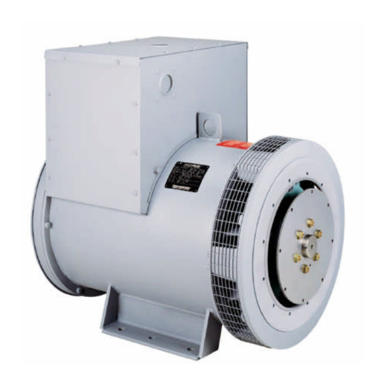
- Page 1 ® MAGNAPLUS GENERATOR 280–430 Frame Installation, Operation, and Maintenance Manual Marathon Electric Mfg. Corp. A Subsidiary of Regal-Beloit Corp. P.O. Box 8003 Wausau, WI 54402-8003 Phone: (715) 675 3359 Fax: (715) 675 8026 www.marathonelectric.com...
-
Page 2: Table Of Contents
CONTENTS When in doubt, ask. Questions are much easier to handle than mistakes caused by a misunderstanding of the Safety information presented in this manual. Receiving and Storage Principles of Operation 3 - 4 Installation 4 - 6 Wiring Connections 6 - 9 RECEIVING AND STORAGE Operation... -
Page 3: Principles Of Operation
PRINCIPLES OF OPERATION PMG (optional) Rotating Assembly PMG Field Exciter Field Exciter Armature Main Field Main Armature (rotor) (stator) (rotor) (rotor) (stator) (in) (in) 3 Phase AC (out) 3 Phase AC (out) Armature (stator) Rotating Rectifier Assembly 3 Phase -- Full Bridge Exciter Field Power Input Power -- Single Phase (DC out) -
Page 4: Installation
(armature). At rated speed, Poor wave shape may adversely effect various loads the main stator’s voltage produced by the residual connected to the generator. Consult Marathon Electric for magnetism of the exciter allows the automatic voltage further information relative to nonlinear loads. - Page 5 A bearing life calculation should NOT DESIGNED FOR THIS PURPOSE. BARRING be performed. Marathon Electric recommends a minimum OVER THE SET WITH THE FAN COULD DAMAGE B-10 life of 40,000 hours. If cog type belts are used, a...
-
Page 6: Wiring Connections
interior of the generator from shavings when drilling or ENVIRONMENTAL CONSIDERATIONS sawing. An approved connector must be used in conjunction with the conduit. To minimize the transmission The MagnaPLUS generator is designed for heavy duty of vibration, it is essential that flexible conduit be used for all industrial applications;... - Page 7 LOW (PARALLEL) WYE CONNECTION VOLTAGE (LOW WYE) L - L L - N HIGH (SERIES) DELTA CONNECTION VOLTAGE (HIGH DELTA) L - L L - N LOW (PARALLEL) DELTA CONNECTION VOLTAGE (LOW DELTA) L - L L - L...
- Page 8 DOUBLE DELTA -- SINGLE PHASE CONNECTION VOLTAGE (DOUBLE DELTA) L - N L - N Note: Single phase KW/KVA ratings are approximately L - L equal to 50% of the generator’s three phase ratings. LOW ZIG ZAG -- SINGLE PHASE (PARALLEL) CONNECTION VOLTAGE (LOW ZIGZAG) Note: Single phase KW/KVA ratings are approximately L - N...
-
Page 9: Operation
DEDICATED SINGLE PHASE CONNECTION HIGH VOLTAGE - SERIES CONNECTED VOLTAGE (DEDICATED) L - N L - N L - L Review all prime mover prestart-up instructions, and OPERATION ensure that all recommended steps and procedures have been followed. Remove any masking materials affixed during painting. PRE-START INSPECTION Inspect the generator, prime mover, and any accessory equipment to ensure that nameplates, and all safety... -
Page 10: Maintenance
The purpose of this initial test with the regulator out of Isolate all conditions that could apply voltage to the the circuit is to detect any wiring mistakes without generator terminals while the generator is at rest. exposing the unit to undue risk. Check all line to line Failure to comply could result in personnel injury or and line to neutral voltages for balanced voltage. -
Page 11: Testing
If the reading drops below the QUALIFIED ELECTRICAL PERSONNEL. LETHAL minimum, the generator should be cleaned and dried at VOLTAGE MAY BE PRESENT AT BOTH THE an authorized service shop. Consult Marathon Electric GENERATOR VOLTAGE REGULATOR for more information. TERMINALS DURING THIS PROCEDURE. CAUTION... -
Page 12: Service
When the positive test probe is connected to the diode's Insulation Test anode and the negative test probe is connected to the diode's cathode (forward biased), the diode will switch on Insulation resistance is a measure of the integrity of the and conduct electricity (figure 3). -
Page 13: Bearing Replacement
CAUTION: clear the locating register on the frame. Lower the shaft extension until the rotor is resting on the main stator core. Failure to remove the exciter field leads from the Continue to pull the bracket free from the bearing. Visually automatic voltage regulator... -
Page 14: Troubleshooting
The first step of troubleshooting is to gather as much information as is possible from operating personnel and Contact Marathon Electric Manufacturing Corporation for individuals present during the failure. Typical information authorization before returning any product. We can not be includes: how long the unit had been operating;... - Page 15 WARNING HIGH VOLTAGES MAY BE PRESENT AT THE GENERATOR’S TERMINALS WHEN THE UNIT IS RUNNING. SOME ACCESSORY EQUIPMENT SUCH AS SPACE HEATERS MAY BE ENERGIZED FROM AN OUTSIDE POWER SOURCE WHEN THE UNIT IS AT REST. TOOLS, EQUIPMENT, CLOTHING AND YOUR BODY MUST BE KEPT CLEAR OF ROTATING PARTS AND ELECTRICAL CONNECTIONS.
- Page 16 GENERATOR PRODUCES LOW VOLTAGE WHEN LOAD APPLIED CAUSE CHECK AND REMEDY Excessive load Reduce load. The load on each leg should be evenly balanced, and rated current should not be exceeded on any leg. Large motor starting or low load Motor starting currents are too large for the generator.
- Page 17 Adjust driver speed and/or generator voltage as necessary to match generator output to load requirements. CAUTION: Compare required voltage, frequency, and KVA with generator nameplate to ensure adequate generator capacity. If in doubt, consult Marathon Electric for information regarding generator capacity.
-
Page 18: Specifications
SPECIFICATIONS MODEL / FRAME SIZE EXCITER RESISTANCE STATOR ROTOR 281, 282, 283, 284 23.0 .120 361, 362, 363 -- three phase 23.5 .120 361, 362, 363 -- dedicated single phase 23.0 .135 431, 432, 433 -- three phase 20.33 .076 431, 432 -- dedicated single phase 18.0 .105... -
Page 19: Parts List & Recommended Spare Parts
PARTS LIST – SINGLE BEARING Typical Generator Cross Section Reference Part Name Reference Part Name Number Number End Bracket (under end cover 360 & 430 frames) Main Stator Bearing Main Rotor O-ring (280 frame only) Rotor Integral Keyway Rectifier Assembly Air Intake Screen (280 frame only) Mounting Adapter (SAE) Exciter Rotor... - Page 20 PARTS LIST – DUAL BEARING Typical Generator Cross Section Reference Part Name Reference Part Name Number Number End Bracket (under end cover 360 & 430 frames) Main Stator Bearing (nondrive end) Main Rotor O-ring (280 frame only) Rotor Integral Keyway Rectifier Assembly Air Intake Screen (280 frame only) End Bracket (drive end)
Need help?
Do you have a question about the Magna Plus 280-430 Frame and is the answer not in the manual?
Questions and answers