
Related Manuals for SST SST-PFB-SLC

Summary of Contents for SST SST-PFB-SLC
- Page 1 SST-PFB-SLC User’s Guide Version 2.04 50 Northland Road Waterloo, Ontario, CANADA N2V 1N3 Tel: (519) 725-5136 Fax: (519) 725-1515 www.sstech.on.ca...
- Page 2 Rockwell Software. All other trade names referenced are trademarks or registered trademarks of their respective companies. SST strives to ensure accuracy in our documentation. However, due to rapidly evolving products, on occasion software or hardware changes may not have been reflected in the documentation.
-
Page 3: Table Of Contents
Contents Introduction ..............1 Purpose of this manual ......... 2 Related Documentation ........ 2 Conventions used in this manual ....3 1.3.1 Special Notation ........3 Warranty ............4 Technical Support ......... 5 1.5.1 Before you call for help ......5 1.5.2 Getting help ........... - Page 4 APS ............. 28 5.1.2 PLC-500 Ladder Logistics ....29 5.1.3 RS Logix 500 ........30 Creating an I/O Configuration in the SST ProfiBus Configuration Tool ......... 31 Creating an I/O Configuration in COM PROFIBUS............33 5.3.1 Mapping the Addresses ...... 35 Uploading the I/O Configuration to the Scanner ..............
- Page 5 Contents DP Master Application Examples ........ 45 Addressing ..........46 32 Discrete Output Module ......46 32 Discrete Input Module ......47 Example: M0/M1 Addressing ...... 47 Example: Accessing Data ......47 Example: Using Flex I/O ......50 Using the Scanner Module as a DP Slave ....53 Slave Received Data ........
- Page 6 SST-PFB-SLC User’s Guide Diagnostics ..............79 Status Register ........... 80 Scanner Firmware Version Number .... 80 DP Master Slave Status Table ....81 DP Master Slave Error Table ...... 82 DP Master Slave Extended Status Table ..82 9.5.1 Reading the Extended Status ..... 83 DP Master Error Information Table .....
- Page 7 Contents Technical Data ............105 Index ................107...
- Page 8 SST-PFB-SLC User’s Guide viii...
-
Page 9: Introduction
Introduction Revision Notes and Exceptions As of Publication Date Exception Note This chapter describes: • the purpose of this manual • related documentation • style conventions used in this manual • warranty and technical support information... -
Page 10: Purpose Of This Manual
SST-PFB-SLC User’s Guide Purpose of this manual This manual explains how to install and use the SST-PFB-SLC scanner. It describes the procedures you use to install, configure, and operate the SST-PFB-SLC scanner. Related Documentation For... Read this Document... Document Number... -
Page 11: Conventions Used In This Manual
Introduction Conventions used in this manual The following conventions are used throughout the manual: • Listed items, where order is of no significance, are preceded by bullets. • Listed items, to be performed in the order in which they appear, are preceded by a number. -
Page 12: Warranty
Maximum liability of SST is the cost of the product(s). Product Returns If it should be necessary to return or exchange items, please contact SST for a Return Authorization number. 50 Northland Road... -
Page 13: Technical Support
SST-PFB-SLC User’s Guide Technical Support 1.5.1 Before you call for help Before calling for technical support, ensure that you have the following information readily available: • SLC module name and serial number • module revision and series, firmware revision, other modules installed •... - Page 14 SST-PFB-SLC User’s Guide...
-
Page 15: Overview
Overview This chapter describes the following: • system overview • how the scanner interacts with the SLC processor • how the scanner interacts with ProfiBus DP I/O modules... -
Page 16: System Overview
SST-PFB-SLC User’s Guide System Overview The SST-PFB-SLC is the ProfiBus scanner for the SLC 500. It enables communication between a SLC processor (SLC 5/03 or later) and DP remote I/O devices on a ProfiBus network. It acts as a ProfiBus DP remote I/O scanner to scan up to 96 slaves. - Page 17 Up to 32 words of data can be configured to be in the input and output files. With the SST ProfiBus Configuration Tool, up to 1000 words of data can be configured in the M0 and M1 files. With COM PROFIBUS, up to 122 words of data can be configured in the M0 and M1 files.
-
Page 18: Hardware Features
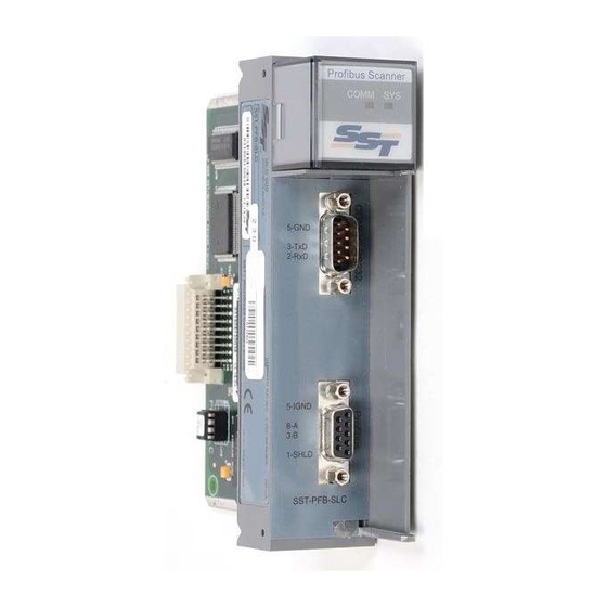
SST-PFB-SLC User’s Guide Hardware Features The scanner's features are shown here. LED information is in section 4.3. Feature Description status LEDs display the communication and system status front label identifies the scanner 9-pin ProfiBus connector for connection to the ProfiBus network... -
Page 19: Leds
2.2.2 9-pin ProfiBus connector The 9-pin ProfiBus connector connects the scanner to the ProfiBus network. 2.2.3 Configuration port Use the configuration port to upload I/O configurations exported from the SST ProfiBus Configuration Tool or Siemens COM PROFIBUS to the scanner. - Page 20 SST-PFB-SLC User’s Guide...
-
Page 21: Quick Start
Quick Start This chapter describes the following: • what tools and equipment you need • preliminary considerations • how to address, configure and program the module • how to wire and install the module • system power-up procedures Note The procedures in this chapter are written with the assumption that the user has a basic understanding of process control, and is able to interpret the ladder logic instructions that control the applications. -
Page 22: Equipment And Tools
SST-PFB-SLC User’s Guide Equipment and tools Have the following tools and equipment ready: • SLC programming equipment • SST ProfiBus Configuration Tool, or Siemens COM PROFIBUS software • communication software • null modem cable • ProfiBus cable to connect the scanner to the ProfiBus network. -
Page 23: Power Requirements
Quick Start Power Requirements Review the power requirements of your system to see that your chassis supports placement of the scanner module. Note The scanner consumes 700 mA @ 5VDC. For modular systems, calculate the total load on the system power supply using the procedure described in the: SLC 500 Modular Style Installation &... -
Page 24: Procedures
SST-PFB-SLC User’s Guide Procedures The setup of the SST-PFB-SLC ProfiBus Scanner is divided into two parts: • Setting up the scanner. • Getting the scanner running. 3.4.1 Setting up the Scanner Warning Ensure that system power is off, before working on or around this equipment. -
Page 25: Getting The Scanner Running
Install the SST ProfiBus Configuration Tool. Run the setup.exe file from the Windows 32 distribution disk. Create your I/O configuration. Refer to section 5.2, Creating an I/O Configuration in the SST ProfiBus Configuration Tool, in this manual for more detailed information. - Page 26 SST-PFB-SLC User’s Guide Issue the ‘Rec2bssXmodem’ command to the scanner serial port to upload the binary I/O configuration to the scanner. Initiate an Xmodem file transfer in the communication software to upload the binary file. 10. Use the exit command to leave configuration mode when the file has been successfully transferred.
-
Page 27: Installation And Wiring
Installation and Wiring This chapter contains the information necessary to: • install the module • insert the module in the SLC chassis • connect the module to the network • power up the module • understand the module LEDs... -
Page 28: Installing The Scanner Module
SST-PFB-SLC User’s Guide Installing the Scanner Module This illustration identifies the chassis and module components described in the procedures in this chapter. Warning Disconnect system power before attempting to install, remove, or wire the scanner. Note The scanner consumes 700 mA at 5 VDC. -
Page 29: Installation
Installation and Wiring 4.1.1 Installation Disconnect power. Align the full-sized circuit board with the chassis card guides. The first slot (slot 0) of the first rack is reserved for the SLC 500 processor. Slide the module into the chassis until the top and bottom latches catch. -
Page 30: Wiring
SST-PFB-SLC User’s Guide Wiring 4.2.1 ProfiBus Wiring The module contains a standard DB9 connector which can be connected to a Profibus bus terminal. The module has no termination but the bus terminal has built-in switchable termination. Pin # Pin Description... -
Page 31: Serial Port Wiring
Installation and Wiring The two physical ends of the network should be terminated. There should be two, and only two, terminators on a network. The recommended cable is Beldon3079A. Examples include: • Siemens 6XV1 830-OAH10 Two Core shielded • Siemens 6XV1 830-OBH10 w/PE Sheath •... -
Page 32: Status Leds
SST-PFB-SLC User’s Guide Connect to the serial port using any communication software such as Windows Terminal or Hyperterminal. The scanner serial port supports any baud rate from 9600 baud to 115 kbaud, with no parity, 8 data bits, 1 stop bit. -
Page 33: Comm Led
Installation and Wiring 4.3.2 COMM LED The COMM LED indicates errors on the network. The following table provides a description of the status of the LEDs. Color Indication a network error has occurred. the LED flashes red at one second intervals. - Page 34 SST-PFB-SLC User’s Guide...
-
Page 35: Dp Master Configuration And Programming
Programming This chapter describes: • configuring the scanner in APS • creating an I/O configuration in the SST ProfiBus Configuration Tool or Siemens COM PROFIBUS • assigning I/O addresses to the slaves • uploading the I/O configuration to the scanner •... -
Page 36: Configuring The Scanner
Select Configure I/O. If you are online, select Read Config to read the configuration, and skip to step 9. Select the slot in which the SST-PFB-SLC is located, then select Modify slot. Select Other and enter the scanner ID (13635). -
Page 37: Ladder Logistics
Select the SLC processor, memory, and operating system. Select the rack number for the scanner (rack 1) and the rack size. Select the slot in which the SST-PFB-SLC is located, and press F5 Select to configure the scanner Select Other and enter the scanner ID code (13635). -
Page 38: Rs Logix 500
In the project tree, double click on I/O Configuration. Set the rack size for rack 1. Highlight the slot in which the SST-PFB-SLC is located Double click on Other in the list of available modules and enter the scanner ID code (13635). -
Page 39: Creating An I/O Configuration In The Sst Profibus Configuration Tool
Creating an I/O Configuration in the SST ProfiBus Configuration Tool The SST ProfiBus Configuration Tool consists of a main view (the network view) and two frames: the Profibus Devices frame and the On-line Browse frame. Both of these are floating frames; drag and drop them to move them anywhere inside the network view. - Page 40 SST-PFB-SLC User’s Guide Find and select your slave device in the Profibus Devices frame. To add this slave device to the DP Network: • Drag and drop it into the network view under the master device. • Click on the Add to Network button on the main toolbar.
-
Page 41: Creating An I/O Configuration In Com Profibus
COM PROFIBUS assigns appropriate values for all the network parameters and includes them in the binary file To use the SST-PFB-SLC with COM PROFIBUS, install the update files for the SST-PFB-SLC in the appropriate COM PROFIBUS directories. To install the files, run the batch file updcomet.bat on the distribution disk and tell it the directory where you are installing the files. - Page 42 SST-PFB-SLC User’s Guide This procedure describes the steps to create a binary file to configure the SST-PFB-SLC as a DP master. In this procedure, the network being configured consists of only Profibus DP remote I/O devices. Refer to the COM PROFIBUS software documentation for more detailed information.
-
Page 43: Mapping The Addresses
DP Master Configuration and Programming Click Configure... to assign the I/O addresses for the slave. These addresses determine where the slave data appears in the SLC. Refer to section 5.3.1, Mapping the Addresses, for detailed information on addressing. Save the configuration file (File/Save) after all the slaves have been configured. - Page 44 SST-PFB-SLC User’s Guide Addresses Q0 to Q255 map to M1:0-127 for inputs and M0:0-127 for outputs. Note Q addresses in the configuration tool are byte addresses while the M0 and M1 addresses in the SLC are word addresses. For analog or word modules, assign addresses on even boundaries.
-
Page 45: Uploading The I/O Configuration To The Scanner
The scanner displays the message: Profibus DP ONLY Copyright (c) 1999 SST, a division of Woodhead Canada Limited For SST-PFB-SLC Card Version x.xx and a, “>” prompt at the terminal. - Page 46 Displays the version number of the firmware running on the scanner RecbssXmodem Upload a DP master configuration exported as a binary file from the SST ProfiBus Configuration Tool Exit Exits terminal mode and restarts module...
- Page 47 DP Master Configuration and Programming Uploading an I/O Configuration to the Scanner To upload the DP master configuration file .bss: Issue the RecbssXmodem command, then initiate an XModem file upload from your communication software. Refer to the documentation supplied with your communication software for more detailed information.
-
Page 48: Network Parameter Errors
SST-PFB-SLC User’s Guide 5.4.1 Network Parameter Errors The following status errors may occur when setting the network parameters. STS_BAD_BAUD STS_BAD_STN_ADR STS_BAD_HI_STN_ADR STS_BAD_TOK_ROT STS_BAD_SLOT_TME STS_BAD_IDLE_1 STS_BAD_IDLE_2 STS_BAD_RDY_TME STS_BAD_QUI_TME STS_BAD_GAP_UPD STS_BAD_TOK_RETRY STS_BAD_MSG_RETRY STS_BAD_TOK_ERR_LIM STS_BAD_RSP_ERR_LIM STS_BAUD_DET_ERROR 5.4.2 Binary File Configuration Errors The following errors occur when configuring the scanner using a binary file generated by your configuration software. -
Page 49: Flash Programming Errors
DP Master Configuration and Programming Error 20h occurs if you are using old firmware with the SST ProfiBus Configuration Tool or when you are using firmware version 1.5x or later with the old beta of the SST configuration tool (ver 0.x). -
Page 50: Fatal Errors
Record the contents of the errInternal and errArg registers and contact technical support at SST. The errInt is stored in the high byte of register 4129 of the m1 file. The errArg is stored in the low byte of register 4130 of the M1 file and also in register 4012 of the M1 file. -
Page 51: Running The Scanner
You are in configuration mode (using the serial port to talk to the scanner) and try to put the SLC in RUN MODE Catastrophic internal failure. Call SST for technical support. Catastrophic failure. Record the flash LED sequence. -
Page 52: Using The Watch-Dog Timer
5.6.1 How the Host Watch Dog works After the SST-PFB-SLC has been reset or powered up, a default time of 100 ms is used for the watchdog period, which exists for communications with the SLC Processor. If the SST-PFB-SLC does not get an update of I/O from the SLC processor with the 100 ms period, the scanner faults. -
Page 53: Dp Master Application Examples
DP Master Application Examples... -
Page 54: Addressing
SST-PFB-SLC User’s Guide Addressing The scanner occupies slot 2 in the SLC rack. The following table shows the modules in the I/O configuration, the address assigned in COM PROFIBUS, and the location of the I/O data in the SLC. Module... -
Page 55: Discrete Input Module
DP Master Application Examples 32 Discrete Input Module The following table shows where the data appears in the SLC for a Siemens ET200B 32DI module mapped at different addresses in COM PROFIBUS (The scanner is in slot 2.). Module starting address in COM PROFIBUS Module data address I0.0... - Page 56 SST-PFB-SLC User’s Guide Sample Program...
- Page 57 DP Master Application Examples Sample continued...
-
Page 58: Example: Using Flex I/O
SST-PFB-SLC User’s Guide The program uses 80 ms and 160 ms internal timers to implement four states, with a combined period of 320 ms. The OSR instructions ensure that the SLC executes the COP instruction only at the start of one of these states. The result is that all four blocks are accessed within the 320 ms combined period of the two timers. - Page 59 DP Master Application Examples The following table shows how to configure the various Flex I/O modules. An entry of 000 means do not configure a length for that slot. Configure the I/O address as a P address so that the data maps into the I or O file in the SLC for fast access, and the status part of the address as a Q address so that the data maps into the M area.
- Page 60 SST-PFB-SLC User’s Guide In the following example, the first module is a 1794-IB16, the second is a 1794-OB16, and the third is a 1794-IE8. The SST-PFB-SLC scanner is in slot 2 of the SLC rack. Module Slot Assigned I Addr...
-
Page 61: Using The Scanner Module As A Dp Slave
Using the Scanner Module as a DP Slave This chapter describes: • how to use the scanner module as a DP slave. -
Page 62: Slave Received Data
SST-PFB-SLC User’s Guide You can configure the scanner module to act as a DP slave to another DP master on the same network. For example, use this feature to pass data in a distributed system or to pass data to or from an operator interface. The DP slave operation can only be configured from the serial port. -
Page 63: Slave Transmit Data
Using the Scanner Module as a DP Slave Slave Transmit Data Transmit data is the data the scanner module sends to the remote master. You can have from 0 to 122 words of transmit data. Transmit data can be configured to be partly in the output file and partly in the M0 file. Up to 32 words of transmit data can be placed in the output file. -
Page 64: Displaying The Dp Slave Configuration
SST-PFB-SLC User’s Guide Displaying the DP Slave Configuration If you issue the ShowSlv command from the serial port, the module displays the DP slave configuration. Example If you use the ShowSlv command after issuing the configuration commands in the previous examples, the scanner displays: DP Slave Configuration: SlvTxLen O:x.31 Len=1 M0:x.1000 Len=100... -
Page 65: Local Station
Configuring the Module as a Slave Using COM Profibus If you are configuring the SST-PFB-SLC as a master with its own slaves and also as a slave to another master on the network, you must create the master files separately. Otherwise, the SST-PFB-SLC is assigned as a slave in its... - Page 66 Using the Scanner Module as a DP Slave...
-
Page 67: Using Fdl
Using FDL... -
Page 68: Fdl (Layer 2) Messaging
SST-PFB-SLC User’s Guide FDL (Layer 2) Messaging The SST-PFB-SLC can send and receive FDL (layer 2) messages. Features include: • supports up to 4 Service Access Points (SAPs) • supports up to 4 message request blocks Messages and SAPs are enabled from the serial port and any required configuration is done from the SLC. - Page 69 Using FDL M0 and M1 Files The scanner uses areas in the M0 and M1 files for FDL message and SAP configuration information and data. M0 offsets 1122-1251 FDL message control/Tx buffer 0 1252-1381 FDL message control/Tx buffer 1 1382-1511 FDL message control/Tx buffer 2 1512-1641 FDL message control/Tx buffer 3...
-
Page 70: Fdl Messages
SST-PFB-SLC User’s Guide FDL Messages To enable FDL messages, issue the EnaMsg command from the serial port while in configuration mode and talking to the scanner. The state of FDL messages (enabled/disabled) is stored in flash when you exit configuration mode. - Page 71 Using FDL To set up a message, set: • bits in the Control/Config register, CntCfg, if necessary If you set bit 2, the scanner sends the message to the high priority queue on the scanner. The scanner maintains two FDL message queues.
- Page 72 SST-PFB-SLC User’s Guide • The message type, or frame control, FrmCntrl. The message type can be one of the following: FC_SDAl Send Data with Ack Lo Pri (SDAL) FC_SDAh Send Data with Ack Hi Pri (SDAH) FC_SDNl Send Data No Ack Lo Pri (SDNL)
- Page 73 Using FDL The scanner sends the message. Wait for the message done bit to be set and check the error bit in word I:31 of the input file. Message block Message done Message error If there is an error with the message, both the done bit and the error bit will be set.
- Page 74 SST-PFB-SLC User’s Guide RspStatus contains the value returned by the LAN controller when it encounters an error. Mask the value with BFh and use the following table to determine the meaning. X indicates “do not care” values in the upper half of the byte.
- Page 75 Using FDL Sample Program...
- Page 76 SST-PFB-SLC User’s Guide Sample Continued...
-
Page 77: Fdl Saps
Using FDL FDL SAPs You can enable up to four Service Access Points (SAPs) on the scanner. You enable SAPs from the serial port, using the ‘SAPBlk’ command. The syntax SAPBlk <blk> <sap> where <blk> is the block number, 0 to 3 and <sap>... -
Page 78: Sap Receive Buffers
SST-PFB-SLC User’s Guide 8.3.1 SAP Receive Buffers Whenever a SAP is updated, the scanner fills in the appropriate receive buffer in the M1 file. Some of the data comes from the source station; some comes from the scanner. Offset Name... -
Page 79: Sap Transmit Buffers
SST-PFB-SLC User’s Guide 8.3.2 SAP Transmit Buffers If you are sending reply data, you must set up an FDL transmit buffer in the M0 file. Offset Name reserved 1642-1648 1772-1778 1902-1908 2032-2038 TxLen 1649 1779 1909 2039 8-129 TxData 1650-1771... - Page 80 SST-PFB-SLC User’s Guide Sample Program...
- Page 81 SST-PFB-SLC User’s Guide Sample Continued...
-
Page 82: Fdl Diagnostic Counters
SST-PFB-SLC User’s Guide FDL Diagnostic Counters The scanner maintains several diagnostic counters for FDL operation. Name Location Description diagLay2MsgOk 4116 FDL messages sent OK errLay2MsgNotOk 4117L FDL message errors diagLay2SapOk 4118 FDL SAP requests processed OK errLay2SapNotOk 4119L FDL SAP errors The scanner increments diagLay2MsgOk whenever it sends an FDL message and receives the appropriate acknowledge or response data. -
Page 83: Fdl Network Parameters
SST-PFB-SLC User’s Guide FDL Network Parameters If you are using the scanner only for FDL, you must also set several network parameters from the serial port before putting the module online. At minimum, set the local station number and the baud rate. If you are sending FDL messages, make sure that the station is active. - Page 84 SST-PFB-SLC User’s Guide Displaying Network Settings To display the current network parameter settings, issue the ShowNet command from the serial port.
- Page 85 SST-PFB-SLC User’s Guide...
- Page 86 SST-PFB-SLC User’s Guide...
-
Page 87: Diagnostics
Diagnostics This chapter describes: • system diagnostics... -
Page 88: Status Register
Record the contents of the errInternal and errArg registers and contact technical support at SST. ErrInt is stored in the high byte of register 4129 of the m1 file. ErrArg is stored in the low byte of register 4130 of the M1 file and also in register 4012 of the M1 file. -
Page 89: Dp Master Slave Status Table
Diagnostics DP Master Slave Status Table The area in the M1 file from 4000 to 4007 contains the status of the slaves, one bit per slave. For example, if the slave at station address 1 is good, bit 1 of register 4000 is set. In addition, if the status of all slaves is good, bit 0 of register 4013 is set. -
Page 90: Dp Master Slave Error Table
SST-PFB-SLC User’s Guide DP Master Slave Error Table The area in the M1 file from 4020 to 4027 shows slaves that are in error, one bit per slave. For example, if the slave at station address 1 is in error, bit 1 of register 4020 is set. -
Page 91: Reading The Extended Status
Diagnostics 9.5.1 Reading the Extended Status To read the extended status of a slave, write the station number to the diagnostic status station select register, register 3828 in the M1 file. The scanner then retrieves the diagnostics for that slave. If the scanner successfully gets the diagnostics, it puts them in registers 3829-3950 and sets the high byte of the diagnostic status station select register to 80h. - Page 92 SST-PFB-SLC User’s Guide Value Cause failure while trying to configure slave slave real ID does not match slave’s configured ID frame delivery problem while updating slave data frame delivery problem while reading slave diagnostics error in diagnostic status byte #1 during configure...
- Page 93 Diagnostics Value Description Invalid response after sending configuration check data to the slave Response to configuration check packet was non-zero length (slave should never return anything) Invalid response after sending the second diagnostic status request to the slave high byte = 03h (frame delivery problem while updating slave data) Value Description error in data update during configuration...
- Page 94 SST-PFB-SLC User’s Guide The bits in station status byte 1 are: Meaning DP slave has been parameterized by another master Slave received an invalid parameter frame, wrong Ident, wrong length, invalid parameters, etc. Invalid response from the slave Master requested a function that the slave does...
-
Page 95: Dp Slave Status Register
Diagnostics The bits in station status byte 2 are: Meaning Slave has been marked inactive by the master reserved The slave has received a Sync command The slave has received a freeze command The slave watchdog has been activated The slave sets this bit to 1 Slave is requesting a diagnostic read. -
Page 96: Dp Slave Error Register
SST-PFB-SLC User’s Guide DP Slave Error Register The scanner module sets the slave error register, register 4018 in the M1 file, to the following values to report various error conditions in its operation as a DP slave. If there are multiple errors, the register contains the value for the last error encountered. -
Page 97: Diagnostic Counters
Diagnostics If the value is SLV_ERR_TX_LEN_MISM, the master has requested data from the slave with a length different from the length configured for the slave. If there is a transmit length mismatch, the card won’t communicate as a slave If the value is SLV_ERR_WD_FACT_INV, one of the two slave watchdog factors is zero, which is not allowed. - Page 98 SST-PFB-SLC User’s Guide Name Location Description diagMinTokHldTime 4106-4107 Minimum token hold time diagMasterUpdate 4108 Master I/O update cycles completed errMasErr 4109L Master->DP slave errors errMasReConfig 4109H Master->DP went offline and had to be reconfigured diagMasScanTime 4110-4111 Master scan time (us)
-
Page 99: General Statistics
Diagnostics 9.9.1 General Statistics These counters relate to the overall operation of the scanner on Profibus. The errLanOffline counter, the high byte of register 4100, increments when the LAN encountered errors and went offline. The diagConf counter, register 4101, counts total confirmations, that is, good replies to messages that this station has generated. -
Page 100: Dp Slave Statistics
SST-PFB-SLC User’s Guide The diagMasMaxScanTime register, registers 4112 and 4113, contains the maximum value that diagMasScanTime has reached since it was last cleared. 9.9.3 DP Slave Statistics These counters relate to the operation of the card as a DP slave. - Page 101 Diagnostics The errNetTout counter, the low byte of register 4127, counts network timeout errors. These errors occur when the network is dead. If a timeout occurs, the scanner enters the claim token state. The errHsa counter, the high byte of register 4127, increments when a station higher than the set high station address is heard.
-
Page 102: Summary Of Diagnostic Locations
SST-PFB-SLC User’s Guide 9.10 Summary of Diagnostic Locations The following tables summarize the locations used. 9.10.1 M1 File Locations 3700-3827 DP Master error information 3828 DP master diagnostic station select 3829-3950 DP master diagnostic status buffer 4000-4007 Slave status table... -
Page 103: Upgrading The Scanner Firmware
Upgrading the Scanner Firmware This chapter describes: • the steps required to upgrade the scanner firmware... - Page 104 SST-PFB-SLC User’s Guide Use the serial CONFIG port on the front of the scanner to upload configuration files to the scanner. The serial cable for a standard PC COM port must have lines 2 and 3 swapped. It doesn’t require any handshaking. Pins 2 and 3 are wired the same as a PC 9-pin COM port.
-
Page 105: Network Parameter Defaults
Network Parameter Defaults This chapter describes: • network defaults... - Page 106 SST-PFB-SLC User’s Guide The following tables show the default values assigned by the scanner for the network parameters. The values depend on: • the baud rate • whether there are repeaters on the network • whether there are FMS devices on the network Idle time 1 is the time the scanner waits after it receives a response before it sends, and corresponds to the Profibus Idle Time.
- Page 107 Network Parameter Defaults No repeater, no FMS Baud Slot Idle Idle Ready rate time time 1 time 2 time Time 9600 19200 93.75 K 187.5K 500K 750K 1.5M No repeater, FMS Baud Slot Idle Idle Ready rate time time 1 time 2 time Time...
- Page 108 SST-PFB-SLC User’s Guide Repeater, no FMS Baud Slot Idle Idle Ready rate time time 1 time 2 time Time 9600 19200 93.75 K 187.5K 500K 750K 1.5M Repeater, FMS Baud Slot Idle Idle Ready rate time time 1 time 2...
-
Page 109: M0 And M1 Files
M0 and M1 Files Note The following is based on information in the SLC 500 Instruction Set Reference Manual, Allen-Bradley publication 1747.6.15, and is provided here for reference. - Page 110 SST-PFB-SLC User’s Guide M0 and M1 files are files that reside in specialty I/O modules only. There is no image for these files in the processor memory. This means that when an application running on the SLC accesses the data, the SLC must go out to the module and read the data.
-
Page 111: Addressing M0 And M1 Files
M0 and M1 Files 12.1 Addressing M0 and M1 Files The addressing format for M0 and M1 files is: Mf:e.s/b where f = file type, 0 or 1 e = slot (1 to 30) s = word (0 to maximum supplied by module) b = bit, (0 to 15) 12.1.1 Restrictions on Using M0-M1 Data File Addresses... -
Page 112: Monitoring Bit Addresses
SST-PFB-SLC User’s Guide 12.1.2 Monitoring Bit Addresses M0 and M1 Bit Monitoring Disabled When monitoring a ladder program in run or test mode, the following bit instructions, addressed to an M0 or M1 file, are indicated as false regardless of their actual true/false logical state. -
Page 113: Technical Data
Technical Data Part number SST-PFB-SLC Function SLC-500 scanner for ProfiBus networks SLC Interface 32 words direct Input and Output data 1000 words of M0, M1 mapped data Environmental storage temperature -40°C to 85°C operating temperature 0°C to 50°C operating RH level 5% to 95%... - Page 114 SST-PFB-SLC User’s Guidel CISPR22 Compliance Marking of this equipment with the symbol indicates compliance with European Council Directive 89/336/EEC - The EMC Directive. This equipment meets or exceeds the following technical standards: This device meets or exceeds the requirements of the following standard: •...
- Page 115 Index diagMasScanTime diagMasterUpdate diagMinTokHldTime ASPC2 PROFIBUS Controller Diagnostic Counters Statistics diagSlaveUpdate diagTokHldTime DP Slave disabling COM ET 200 DP Slave Statistics COM ET 200 Address Assignment Errors COM ET 200 Configuration Errors email COMM LED errDblTok errFifo errHsa errInternal diagConf errInvReqLen diagInd errLanOffline...
- Page 116 SST-PFB-SLC User’s Guide errMasErr Hyperterminal errMasReConfig errNetTout errNotOk Error Information Table I/O Configuration 31, 33 errPasTok creating errRespErr uploading errRxOverun errSlvErr errSlvTout errStn Mapping Addresses errSyniErr masError Extended Status Master Block Statistics reading Multiple Masters Extended Status Table pfbInitCtrs Fatal Errors...
- Page 117 Index Uploading the I/O Configuration Version Number Web site Wiring Serial Port...
Need help?
Do you have a question about the SST-PFB-SLC and is the answer not in the manual?
Questions and answers