Table of Contents
Advertisement
Torit
Installation
®
and Operation Manual
Torit Dust Collector
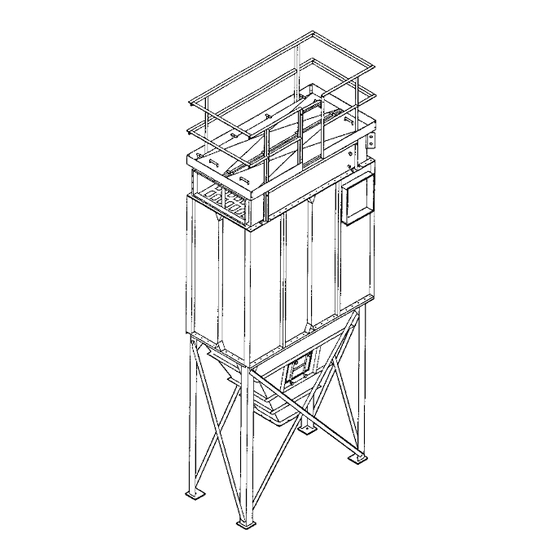
Models HPW, HPT, and HPH
Includes Installation, Operation, and Service Instructions
HPW
HPT
HPH
IMPORTANT
This manual contains specific precautionary statements relative to worker
safety in appropriate sections. Read this manual thoroughly and comply as
directed. It is impossible to list all of the potential hazards of dust control
equipment or systems. It is imperative that use of the equipment be discussed
with a Torit representative. Personnel involved with the equipment or systems
should be instructed to conduct themselves in a safe manner.
Donaldson Company, Inc. © 1995
IOM-29349-00
1
Revision 5
Advertisement
Table of Contents

Related Manuals for Torit HPW

Summary of Contents for Torit HPW
- Page 1 It is impossible to list all of the potential hazards of dust control equipment or systems. It is imperative that use of the equipment be discussed with a Torit representative. Personnel involved with the equipment or systems should be instructed to conduct themselves in a safe manner.
-
Page 2: Notes And Cautions
US Government Printing Office Washington D.C. 20402 Phone: (202) 783-3238 As always, if you have any questions about your Torit dust collector, do not hesitate to contact your local sales representative or the Torit headquarters office. Donaldson Company, Inc. © 1995... -
Page 3: Table Of Contents
Platform and Handrails ......19 of Dwyer Instruments, Inc. ® 2.6.8 Ladder/Cage ..........20 2.6.9 Light Pack (HPW Only) ......20 2.6.10 Blower Fan Mounting Instructions ....21 2.6.11 Damper Pack ..........23 Electrical Installation ......... 23 2.7.1 Electrical Operation ........24 2.7.2 Solid-State Control Timer Specifications .. -
Page 4: Figure 1 - Typical Installation View
* Asterisk items (*) are not included with Dust Collector. * Sprinklers. * Explosion Relief Panels. * Air Line to Manifold * Solenoid Electrical Connection * Power Supply Disconnect Switch Solid-State Control Timer * Air Supply Line * Air Regulator Hopper * Air Filter (Bleed Type) * Blower Fan with Transition... -
Page 5: Introduction
Operational Explanation Introduction The Torit HPH, HPT, and HPW are used for 1.1.1 Normal Operation the collection of airborne dust and particulate. (See Figure 2) As part of a manufacturing process, the HP collector series provides highly efficient, During normal operation, dust-laden air enters continuous, on-line dust collection. -
Page 6: Filter Cleaning
• Ladder Cages minimize freight costs, some components may be • Air Locks shipped unassembled and nested. On most • Tubesheet HPW/T models, the clean air plenum, dirty air • Filter Tubes plenum, and hopper/support weldment are • Filter Cages unassembled. -
Page 7: Equipment/Tools Required
Equipment/Tools Required Preinstallation (See Figure 1) The following is a list of typical tools and equipment required to install and assemble an The HP dust collector is usually mounted on a HP dust collector: reinforced concrete foundation. However, roof mounting is also possible. When calculating for •... -
Page 8: Assembly Of Standard Equipment
• A crane is recommended for the components on specification drawings unloading, assembly, and installation furnished by Torit. Spreader bars are of the dust collector. recommended between lifting cables; shallow cable angles should be avoided. -
Page 9: Erection (Major Collector Components)
2.5.2 Erection (Major Collector Components) HPT/W Units Only - (Hopper & Legs) CAUTION 1. The HPT/HPW hopper/leg arrangements come totally assembled. Do not disconnect crane until the lifted 2. Lift the hopper/leg assembly, using a crane, component is securely fastened in place. -
Page 10: Figure 3 - Hopper Joint And Leg Attachment
HPH Units Only - (Hopper & Legs) Position the outside angle of the cross (See Figures 3 and 4) bracing and bolt in position. Where the two angles cross, bolt through each hole with a 1. HPH units have unassembled leg sets. bolt, washers, and nut. -
Page 11: Filter Tube Installation
Boltsafe™ Several filter medias are available to meet the hardware provided. filtration needs for many different types of dust. Contact your local Torit representative for assistance in choosing the correct media for NOTE your dust collection requirements. -
Page 12: Figure 6 Filter Tube Installation
3. Remove the crane from the collector. blank end of the tubesheet. HPT/HPW Cabinet Assembly If a platform or handrail is going to be attached to the collector, refer to Section 2.6.7, Platform and Handrails before continuing. -
Page 13: Assembly Of Optional Equipment
Assembly of Optional Equipment 4. Using a crane, lift the clean air plenum into position over the filter section. Using drift pins, align the holes in the flanges of the 2.6.1 55-Gallon Drum Cover Pack With or filter and clean air sections and lower onto Without Slide Gate (See Figures 7 and 8) ) ) ) ) the filter section. -
Page 14: Transition Pack
3/8" bolts, washers, and the AN valves built by Torit. There are four and nuts as shown in Figure 7, Hose Drum sizes available 18" to 8", 18" to 10", 18" to Cover Pack with Gate. -
Page 15: Transition And Airlock
2.6.3 Transition and Airlock electrical connections, and future maintenance of the rotary airlock. (See Figure 9) 4. Apply the sealant supplied with the rotary Do not use a transition and airlock on a single airlock to the top flange. opening trough outlet hopper. 5. -
Page 16: Magnehelic Gage
2. Prior to mounting, plug the pressure ports on longer than the other. If more tubing is the back of the Magnehelic gage using the required, please contact your local Torit two 1/8" NPT pipe plugs supplied with the representative. Once the mounting bracket gage. -
Page 17: Photohelic Gage
2.6.5 Photohelic Gage 4. Connect the tubing to the high pressure and low pressure port fittings located on the (See Figures 11, 12, and 13) Magnehelic gage. The high pressure port tubing is attached to the pressure fitting The Photohelic gage is an optional feature on mounted in the dirty air chamber (filter the HP series collector. -
Page 18: Figure 12 Photohelic Gage Wiring Diagram
Remember that the tubing will have to be cut and that one piece may be longer than the other. If more tubing is required, please contact your local Torit All parts shown in Figure 11 (except mounting representative. Once the mounting bracket... -
Page 19: Level Indicator
6. Zero and maintain Photohelic gage per operating and maintenance instructions provided by the manufacturer of the The platform is offered on the HPH and HPW Photohelic gage. collectors. Mounting brackets have been supplied which are used to attach the platform 7. -
Page 20: Ladder/Cage
2.6.9 Light Pack (HPW Only) The light pack is offered for use in the walk-in section of the HPW collector. The weatherproof light switch is located outside of the collector. The light is located inside the clean air plenum and is attached to a bracket located in the ceiling of the plenum. -
Page 21: 2.6.10 Blower Fan Mounting Instructions
6. Lift the motor wheel assembly into position over the housing and lower. Determine the local Torit representative . proper location for the electrical junction box on the side of the motor. Align the holes... -
Page 22: 2.6.11 Damper Pack
2.6.11 Damper Pack (See Figure 15) 2. Align the damper onto the edge of the The damper pack is offered for all Torit power blower housing. The damper has predrilled packs. The damper fastens to the exhaust side holes which should be used as pilot holes to of the power pack and is used to adjust the locate the self-drilling screws. -
Page 23: Electrical Installation
Blower Housing (Ref) Lever Wingnut Figure 15 Damper Assembly Electrical Installation (See Figure 16) Using wiring diagram supplied with control CAUTION timer, make proper connections to blower motor starter, solid-state control timer, and solenoid • All electrical work must be done by a valves. -
Page 24: Electrical Operation
208/230/460 Volt 60 Hz/3 Phase 115V Start Stop ITGS L1 L2 1 2 3 4 5 6 4FU/3Amp Wiring By Torit 460V Wiring By Others 105 TO 135 VAC 50-60 Hz Solenoid Valves 115V Figure 16 Solid-State Control Timer Wiring Diagram... - Page 25 This cycle is continuous unless an auxiliary little ON time can cause shortened filter control such as the Photohelic pressure switch or tube life. Consult with your local Torit a 1TGS toggle switch is used to control the representative. timer (see Figure 16, Solid-State Control Timer Wiring Diagram).
-
Page 26: Installation-Compressed Air Supply
• It is important that the compressed air filter and automatic condensate valve (not supply be both oil and moisture free. supplied by Torit) should be installed in the Contamination in the compressed air compressed air supply line. Locate these... -
Page 27: Prestart-Up Check
On hoppers with drum Pulse ON time can be checked or adjusted by arrangements, make sure all the connections consulting your local Torit representative. are airtight (see Figure 7, Hose Drum Cover Pack with Gate, Figure 8, Hose Drum Cover... -
Page 28: Operating Checks
Operating Checks At a low operating pressure drop, you may want to raise to a higher pressure drop level. Monitor exhaust after the filters have been Increase the OFF time between pulses on the exposed to dust and maintained a dust cake. solid-state control timer. -
Page 29: Dust Removal
Dust Removal (55-Gallon Drum Only) Compressed Air Components CAUTION NOTE Do not let the dust storage containers Compressed air can be dangerous. overfill. It can cause poor collector Before attempting service, shut off plant performance and create an extensive clean air supply to dust collector and up due to overflow of dust when removing depressurize air manifold. -
Page 30: 7.0 Troubleshooting Guide
7.0 TROUBLESHOOTING GUIDE POSSIBLE CAUSE REMEDY TROUBLE A. Blower fan and motor do 1. Wiring. not start. 1a. Rewire per local and a. Proper wire size not national codes for proper used for motor. wire size. 1b. Check and correct internal b. - Page 31 Figure 6, Filter Tube Installation). 2. Filter tube damage, tears, 2. Replace the filter tubes. or holes in the fabric. Use only Torit filter tubes (see Section 2.5.2, Filter Tube Installation, Figure 6, Filter Tube Installation and reference Replacement Parts List).
- Page 32 7.0 TROUBLESHOOTING GUIDE POSSIBLE CAUSE REMEDY TROUBLE 1. Check fan rotation. The fan D. Insufficient airflow. 1. Fan rotation backwards. rotation should be clockwise, looking down at the top of the blower fan motor (see Section 4.0, Start-Up and Figure 14, Blower Transition Assembly).
- Page 33 4. Filter tubes plugged with particulate. a. Filter tubes need to be 4a. Remove and replace using replaced. only Torit filter tubes (see Figure 6, Filter Tube Installation and Replacement Parts List). b. Lack of compressed 4b. Check compressed air air.
- Page 34 7.0 TROUBLESHOOTING GUIDE POSSIBLE CAUSE REMEDY TROUBLE 5. Pulse valves are not D. Insufficient airflow (contd). functioning. a. Pulse valves are leaking 5a. Lock out all electrical compressed air. power to the HP and bleed off the compressed air supply. Check for debris, valve wear or diaphragm failure by removing the diaphragm cover on the...
- Page 35 Notes Donaldson Company, Inc. © 1995...
-
Page 36: Parts Ordering Information
EXPRESS OR IMPLIED ARE HEREBY EXPRESSLY EXCLUDED AND DISCLAIMED. Parts and Service Program For genuine Torit-Built replacement filters ® and parts, call the Torit Express Line: 800-365-1331 Parts Ordering Information When ordering parts, give model number and serial number, part number, description, and quantity of parts desired.
Need help?
Do you have a question about the HPW and is the answer not in the manual?
Questions and answers