Table of Contents
Advertisement
Quick Links
EFIS System - Engine Monitoring System – Moving Map
Before installing the monitoring system, READ THE LIMITED WARRANTY / AGREEMENT. There is information in the
Limited Warranty / Agreement that may alter your decision to install this product. IF YOU DO NOT ACCEPT THE TERMS
OF THE LIMITED WARRANTY / AGREEMENT DO NOT INSTALL THE PRODUCT. The product may be returned for a
refund if you do not accept the terms of the Limited Warranty / Agreement.
Before starting the installation, make sure that your planned installation will not interfere with the operation of any
controls. The installer should use current aircraft standards and practices to install this product. Refer to AC 43.13-2A,
Acceptable Methods, Techniques, and Practices - Aircraft Alterations and AC 43.13-1B, Acceptable Methods, Techniques,
and Practices--Aircraft Inspection and Repair.
Advanced Flight Systems Inc. www.Advanced-Flight-Systems.com
AF-3400s, AF-3500s, AF-4500s
Patents 6,271,769 B1 and 6,940,425
User Guide and Installation Manual
Version 7.3
09/23/2011
IMPORTANT PRE-INSTALLATION NOTICE
Experimental instrument limited to use in experimental aircraft.
Not approved for use in aircraft with FAA type certificates.
PHONE: (503) 263-0037
FAX: (503) 263-1138
Advertisement
Table of Contents
Troubleshooting

Subscribe to Our Youtube Channel
Summary of Contents for Advanced Elements AF-3500s
- Page 1 AF-3400s, AF-3500s, AF-4500s EFIS System - Engine Monitoring System – Moving Map Patents 6,271,769 B1 and 6,940,425 User Guide and Installation Manual Version 7.3 09/23/2011 IMPORTANT PRE-INSTALLATION NOTICE Before installing the monitoring system, READ THE LIMITED WARRANTY / AGREEMENT. There is information in the Limited Warranty / Agreement that may alter your decision to install this product.
-
Page 3: Af-3400S, Af-3500S, Af-4500S Post Installation Check
AF-3400s, AF-3500s, AF-4500s Post Installation Check CAUTION: Do not fly the aircraft until the following check list has been completed. Never Power the system with an automotive battery charger and the aircraft battery disconnected. Before Power is Applied for the First Time □... - Page 4 First Engine Start □ With relay protection diodes installed, your AFS screen(s) can be turned on before the engine is started. □ After the engine has started, verify oil pressure and temperature. If none is indicated SHUT DOWN the engine. Verify all wiring and consult your local A&P, the engine manufacturer, and/or AFS technical support.
-
Page 5: Limited Warranty / Agreement
LIMITED WARRANTY / AGREEMENT Advanced Flight Systems Inc. (“AFS”) warrants its aircraft monitoring system instrument and system components to be free from defects in materials and workmanship for a period of one year commencing on the date of the first flight of the instrument or one year after the invoice date, whichever comes first. - Page 6 THIS PAGE INTENTIONALLY LEFT BLANK...
-
Page 7: Table Of Contents
Table of Contents AF-3400s, AF-3500s, AF-4500s Post Installation Check ___________________________________ 1 LIMITED WARRANTY / AGREEMENT __________________________________________________ 3 INTRODUCTION ________________________________________________________________________ 9 SYSTEM OPERATION ______________________________________________________________ 10 Power On / Off ________________________________________________________________________ 10 Battery Operation _____________________________________________________________________ 10 Screen Selection _______________________________________________________________________ 11 Enable/Disable Pages ___________________________________________________________________________ 12... - Page 8 Airspace ______________________________________________________________________________________ 44 Track Mode ___________________________________________________________________________________ 44 Map Database Files _____________________________________________________________________________ 45 Traffic Display _________________________________________________________________________ 46 Zaon XRX _____________________________________________________________________________________ 47 Garmin GTX-330 _______________________________________________________________________________ 47 ADS-B Traffic __________________________________________________________________________________ 47 To prevent seeing yourself called out as traffic (ghosting), connect one of the Serial outputs of the GTX-330 configured as REMOTE + TIS to Pin 33 of the ADS600-B box.
- Page 9 Propeller RPM Sensor Installation ________________________________________________________ 77 Oil Temperature Sensor Installation _______________________________________________________ 77 Amp Transducer Installation _____________________________________________________________ 78 Pressure Transducer Installation __________________________________________________________ 79 Oil Pressure Transducer Installation _______________________________________________________ 79 Fuel Pressure Transducer Installation ______________________________________________________ 79 Fuel Flow Transducer Installation _________________________________________________________ 80 Manifold Pressure Transducer Installation __________________________________________________ 81 Fuel Tank Level Sensor __________________________________________________________________ 82 Float Type ____________________________________________________________________________________ 82...
- Page 10 APPENDIX J: Troubleshooting _____________________________________________________ 104 GNS-430W/530W - EFIS - Autopilot - ARINC Interface Troubleshooting _________________________ 105 APPENDIX K: Vertical Power VP-X/PRO Interface _____________________________________ 110 APPENDIX L: Flight Director/AF-Pilot Procedures flying an Approach ______________________ 111 Flying an LPV Approach ________________________________________________________________________ 111 Flying an ILS Approach _________________________________________________________________________ 115 APPENDIX M: SCHEMATICS ________________________________________________________ 116 Registration Information _________________________________________________________ 121...
-
Page 11: Introduction
INTRODUCTION Advanced Flight Systems Inc. manufactures three different size EFIS and Engine Monitor systems. The AF-3400 uses a 6.5” display and the AF-3500 and AF-4500 use an 8.4” display. The new “s” CPU systems utilize our new high speed CPU and support Synthetic Vision. The systems can be purchased as an EFIS only “EF”, Engine Monitor only “EM”, Multi Function Display “MFD”, or as a single screen with both EFIS and Engine Monitor boards installed “EE”. -
Page 12: System Operation
Knobs and Buttons The AF-3400 and 3500 have 5 buttons and one rotary knob with a push button for data input. The AF-4500 has a left rotary knob, 5 buttons and one rotary/joy stick knob on the right side with a push button for data input. -
Page 13: Screen Selection
Screen Selection You can rotate through the enabled screens on the unit by pressing the [PAGE] button. EFIS EFIS & EMS EFIS - EMS - MAP EFIS & MAP... -
Page 14: Enable/Disable Pages
AIR and EMS (non “s” CPU only) Six-Pack Panel Page ("s" CPU) Enable/Disable Pages You can select what pages are in the screen rotation from the [EFIS] -> [Settings] -> [More] menu by pressing the <Page List> knob button. The knob is used to enable or disable each item. After selecting the desired pages be sure and press the [SAVE] button. -
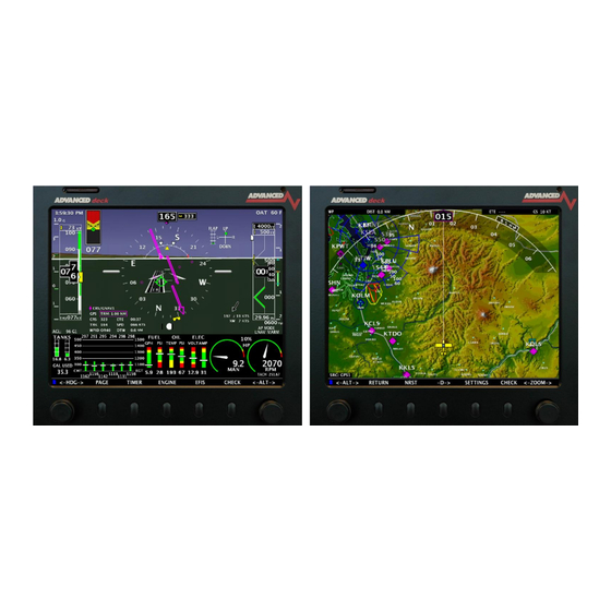
Page 15: Efis Flight Display
EFIS Flight Display Magnetic Heading Heading Bug Setting Current G’s Vertical Speed Airspeed Bug Setting Altitude Bug Setting Pitch Angle Standard Rate Turn Roll Angle G METER Tape Vertical Speed Tape True Airspeed Baro Set Slip Ball Wind AHRS Alignment (Gyro) When power is applied to the system the EFIS display will have a large RED X while the AHRS in initializing. -
Page 16: Screen Dimming
Screen Dimming The screen can be dimmed from the Checklist page by turning the right knob anytime the word DIM is displayed. If DIM is not displayed press the knob and select DIM from the list. Barometric Pressure/Altitude The current barometer setting is displayed in the box below the altitude tape. The value is shown in either inches of Mercury or millibars. -
Page 17: Heading - Efis Dg
Heading – EFIS DG This heading is displayed like a standard slaved directional gyro. The digital readout in the pointer shows your current heading. If the EFIS DG is red, the heading should not be relied on and you should check the magnetometer wiring. Skid/Slip Ball (Inclinometer) The skid/slip ball works like any standard mechanical gauge. -
Page 18: Flight Path Marker
Flight Path Marker The green flight path marker (FPM) or velocity vector shows where the aircraft is actually moving. Think of it as a visual representation of GPS Track. The green target will only be centered under steady state flight conditions with no wind. Usually the target will be moving around the display showing where the airplane is going, not where the nose is pointed. -
Page 19: Clock/Timer Operation
After reaching the Selected Altitude the Bug changes from White to Yellow, and the voice alert “MINIMUMS” is generated. 100’ > Altitude > MDA Bug Altitude < MDA Bug “MIMIMUMS” Altitude > 100’ of MDA Bug Airspeed Bug The Airspeed Bug can be turned on and off from the [EFIS] -> [NAVIGATION] -> [BUGS] ->... - Page 20 Timer Functions The system has a count-down and count-up timer that is accessed by pressing the [TIMER] button in the main menu. The timer value is adjusted with the knob and controlled using the buttons: [START] [STOP] [RESET] [UP/DWN] [ADJ] The Up or Down mode is displayed with an arrow on the screen.
-
Page 21: Angle Of Attack (Aoa)
Angle of Attack (AOA) See Ap p end ix I: AO A Pre ssure Port Loc a tion The EFIS c a n d isp la y a n AOA if yo u ha ve insta lled the op tiona l AOA system . Yo u w ill need to p erform a n in flig ht AO A c a lib ra tion if your unit ha s not b een loa d ed w ith p rec a lib ra ted AO A d a ta . - Page 22 THIS PAGE INTENTIONALLY LEFT BLANK...
-
Page 23: Efis Aoa Calibration Check List
EFIS AOA CALIBRATION CHECK LIST EFIS AOA LANDING CONFIGURATION CALIBRATION CALIBRATION AIRCRAFT LOCATION ..... AIRBORNE CHECK LIST FLAPS/GEAR ....CONFIRMED DOWN EFIS_cklst.doc 09/2010 rev 3 EFIS AOA DISPLAY ON ......... ON paper color Green AOA CAL Button ....... PUSH/RELEASE CONFIRM ...... - Page 24 THIS PAGE INTENTIONALLY LEFT BLANK...
-
Page 25: Synthetic Vision
Synthetic Vision Synthetic Vision (SVN) gives users a forward looking perspective of the terrain ahead. This includes mountains, rivers/waterways, obstacles and runways. The Synthetic Vision database requires a Map Data card be installed in the unit. While the mapping option isn't necessary for SVN to work, the two share the same databases on the Map Data card. - Page 26 TAWS Settings Instrument Calibration: 35: Synthetic Vision 3. Terrain Warning (TAWS) ON/OFF - Enables/Disables terrain shading based on altitude 4. TAWS Airspeed Shutoff (KTS) - Sets the airspeed at which TAWS is disabled (for landing). Traffic Display If a traffic device is connected to your EFIS monitor, the traffic will be displayed on the SVN. Traffic shown must be within 6nm of your aircraft and within the 60 degree view cone of the SVN 30 degrees on either side of your current heading).
-
Page 27: Highway In The Sky (Hits)
Highway in the Sky (HITS) Any EFIS system with Synthetic Vision is capable of displaying Highway in the Sky (HITS). HITS is the artificial generation of boxes that direct the pilot towards a programmed navigation course set by the GPS. HITS is depicted as magenta boxes in the synthetic vision. - Page 28 Currently HITS boxes are not drawn for a descent. If the ALT bug is moved to select a lower altitude, the HITS boxes will descend to that altitude, however a vertical descending path will not be drawn. In the screenshot above, the aircraft altitude is 8,000ft, however the ALT bug (and HITS boxes) are drawn at 7,000ft.
-
Page 29: Efis Navigation (Hsi)
EFIS Navigation (HSI) Co urse Nee d le To/From Identifier Bearing Needle Target Vertical Speeds Course Source Bearing Source NAV Type FD/Autopilot Mode (VOR/GPS) The EFIS can display an HSI when connected to a Nav radio, GPS, or GPS Navigator. The system has two main navigation needles;... -
Page 30: Gps Navigation Display
GPS Navigation Display Vertical Deviation Pointer The Vertical Deviation Pointer (VDP) can be displayed from a WAAS GPS to indicate the baro-VNV vertical deviation when Vertical Navigation (VNV) is being used. The VDP should change to a diamond once you are on the approach and receiving glide slope information. - Page 31 (Distance to Waypoint) DTW displays the nautical miles to the current GPS waypoint. (Speed) SPD displays the current ground speed in nautical miles per hour. WPID (Waypoint Identfier) WPID displays the current waypoint ID from the GPS.
-
Page 32: Vor Navigation Display
VOR Navigation Display To/From Indicator OBS Setting VOR Frequency The Green course indicator points to the current course you have selected using the OBS setting. The OBS setting can be set using the knob on the EFIS when <-CRS-> is displayed over the knob (press the knob if CRS is not displayed). - Page 33 ILS Na viga tion Displa y Runway Heading Localizer CDI Glide Slope VDI ILS Frequency AP/FD Mode You should always set the ILS inbound Approach Course using the CRS knob selection. If the Nav Radio is tuned to an ILS frequency you should use the CRS setting to select the inbound approach course.
-
Page 34: Internal Flight Planning
Internal Flight Planning (Requires Version 8 software or later) AF-3000s/4000s series displays have an internal flight planning feature, eliminating the requirement for an external GPS to provide flight plan waypoints. Only a basic GPS with NMEA data output is required to utilize this feature (though it can still be used with any GPS navigator as well). - Page 35 To remove a waypoint in the flight plan, press [EDIT] and use the cursor to highlight the waypoint, press [REMOVE] Activating the Flight Plan After the flight plan has been created, pressing the ACTIVATE button will change the EFIS navigation source to follow the internal flight plan.
-
Page 36: Autopilot Control / Flight Director
Autopilot Control / Flight Director Note: There is a separate AF-Pilot Installation Manual found on the AFS website. Current AP Mode Autopilot Control For the autopilot to follow the EFIS commands you will need an autopilot that is capable of GPSS and GPSV ARINC steering commands. - Page 37 The AF-Pilot has the following modes controlled from the buttons on the face of the autopilot. [AP] - Autopilot control mode. Pressing the AP button will cause the autopilot to turn on and follow the current ground track and the current vertical speed of the aircraft. The EFIS settings and controls will not have any effect on the autopilot.
- Page 38 EFIS Flight Director/Autopilot Turning on the AP/FD Mode The flight director can be turned on from the following menu: [EFIS] -> [AP/FD] -> [FLTDIR ON/OFF] The wings that come up when the flight director is enabled will show the aircraft positioning to follow. All the pilot has to do is keep the triangle in the wings as they move to follow the commanded source.
-
Page 39: Autopilot / Flight Director Control Settings
Autopilot / Flight Director Control Settings [EFIS] -> [AP/FD] -> [Settings] LATERAL EFIS Autopilot Control Settings Range (.01 – 2.0) Roll GAIN The LAT Gain setting controls how fast the aircraft will respond to errors in track or heading. With too low of a setting the aircraft will hunt slowly and appear slow to respond in roll. - Page 40 LAT ARM Localizer Aircraft will follow the heading bug on the HSI until the CDI needle deflection is less than 80% AND the Current aircraft heading is within 30 degrees of the CDI course. The AP/FD status on the EFIS will show ARM unit switching to NAV mode. Aircraft will follow the heading bug on the HSI until the CDI needle deflection is less than 80% AND the Current aircraft heading is within 90 degrees of the CDI course.
- Page 41 Autopilot / Flight director in ARM mode. AP MODE The AP/FD is currently tracking the Heading and Altitude Bugs. The AP/FD Mode text shows L-ARM and V-ALT, the Flight director wings are yellow indicating that it is being controlled from the Bugs As soon as the green VOR CDI needle moves to within 80% and the heading is within 30 degrees of the CDI course, the FD wings will change to green and the status will change to L-NAV.
- Page 42 The FD wingtip color indicates the current vertical source. In this picture the FD wings are green indicating that the lateral mode is being controlled by the NAV radio, the tips are yellow indicating that the vertical mode is from the altitude bug. For the autopilot to follow the EFIS commands it will need to be in GPSS and GPSV mode.
-
Page 43: The About Page
The ABOUT Page [CHECK] -> [MAINT] -> [ABOUT] This page contains a lot very important information about your system. System Info contains your system Serial Number. This is very important to have when you call AFS for technical support. Next is your software version information, IP address, and installed keys. -
Page 44: Moving Map Display
Moving Map Display GPS Track Current Waypoint Current Zoom Level METAR Symbol Class D Airspace Future TFR from XM Major Road Intersection Map GPS Source XM Weather Age The system can display a moving map if you have purchased and installed the optional Mapping package. -
Page 45: Map Data Source
The moving map can be displayed as a partial screen along with the EFIS and/or Engine Monitor or as a complete page. You can also select if the airspeed and altitude tapes and engine monitor are displayed on the map from the [MAP] ->... -
Page 46: Airport Info
Airport Info Pressing the [INFO] button from the map menu will bring up multiple pages of airport info, including runways, frequencies and airport information. Airspace Airspace is displayed on the moving map along with it vertical boundaries in a similar format to a sectional chart. -
Page 47: Map Database Files
Map Database Files The moving map uses the following database files stored on the SD card, the SD card must be kept in the EFIS for the map to work. : File Name Description Update Frequency AFSTERUS.AFM Terrain height information for the US When Required AFSVECUS.AFM Vector data for US roads/rivers/lakes/cities... -
Page 48: Traffic Display
Traffic Display WARNING: Traffic information displayed on the Map is provided for visually assisting in acquiring other aircraft. The aircraft should be maneuvered based only upon ATC guidance or positive visual acquisition of conflicting aircraft. Traffic 1,100ft above CAUTION Traffic same Altitude Traffic 1,200ft above descending... -
Page 49: Zaon Xrx
Zaon XRX XRX detects up to three threat aircraft from within your cockpit using a cutting-edge, proprietary, self-contained antenna design. With direction, locating and identifying traffic is simple and easy, and traffic information is displayed on the EFIS Map page. XRX delivers the three "dimensions" of traffic information that pinpoints where traffic is located: direction, range and relative altitude. -
Page 50: Garmin Gts-8Xx Tcas System
Garmin GTS-8xx TCAS System The Garmin GTS-8xx TCAS System is a fully self-contained active traffic system which will interface to your EFIS display. Please see the Traffic ARINC Adapter Wiring Diagram for wiring and configuration. ARINC output speed on the GTS-8xx MUST be configured for LOW speed! Note: A special TCAS ARINC adapter is required, please contact AFS for more information. -
Page 51: Weather Display
Weather Display CAUTION: NEXRAD weather data should only be used for long-range planning purposes. Inherent delays and relative age of the WX data can be experienced. NEXRAD weather cannot be used for short-term weather avoidance. NEXRAD High resolution radar image of radar reflectivity and lighting strikes. Reflectivity is the amount of transmitted power returned to the radar receiver. -
Page 52: Xm Weather
site cannot depict high altitude storms at close ranges. It has no information about storms directly over the radar site. • When zoomed in a square block on the display represents an area of 2 ½ miles. The intensity level reflected by each square represents the highest level of NEXRAD data sampled within the area. - Page 53 Screen Configuration Settings One of the screens in the aircraft needs to be configured as the Weather Master and any additional screens should be set to Slave or Offline. Currently we do not support weather on both the new “s” CPU along with the older non “s” CPU on the same network.
-
Page 54: Ads-B Weather
XM Weather Diagnostics [CHECK] -> [MAINT] -> [ABOUT] The ABOUT p a g e d isp la ys p ertinent inform a tion a b out the sta tus o f yo ur XM Wea ther rec eiver. Weather Status shows information for diagnosing weather module problems. Mode: Shows the mode of that particular screen (MASTER or SLAVE). - Page 55 ADS-B Status Information [CHECK] -> [MAINT] -> [ABOUT] The ABOUT p a g e d isp la ys p ertinent inform a tion a b out the sta tus o f yo ur ADS-B Wea ther rec eiver. Weather Status - Shows status information about the ADS-B interface. Not Parsing ADS-B Weather - The EFIS is not receiving FIS-B weather data ADS-B Mode - Displays either Master or Slave mode (Unit wired to the ADS-B device will be Master) Ownship Count - Number of messages the EFIS is receiving from the ADS-B device.
-
Page 56: Ifr Approach Plates
IFR Approach Plates The EFIS Map page has the ability to display an IFR approach plate if your data card contains a CHARTS directory and you have the approach plate file for the selected airport. Current approach plates are available for purchase from the Advanced Flight Systems web store. -
Page 57: Engine Monitor Display
Engine Monitor Display The system can display the engine monitor on the bottom of the main EFIS page or as a full Engine page if the system has one of the following: 1. The screen has an engine monitor board installed in the case. 2. -
Page 58: Fuel Flow Calibration
Fuel Flow Calibration The accuracy of the fuel computer is affected by the value of Counts per .01 gals (K Factor). The Counts per .01 gals (K Factor) sets the calibration of the instrument to match the flow transducer and the variations in the installation. After running a tank of fuel use the following formula to adjust the accuracy. -
Page 59: Power Display
TANKS FILLED You can set the fuel computer to the programmed full tanks by pressing one of the following buttons in the fuel computer: 1. [FILL MAINS] If only the main tanks have been filled 2. [FILL ALL] If the main and tip tanks have been filled WARNING: If you press [FILL ALL] and have not added fuel to the tip tanks the fuel computer calculations will be incorrect... - Page 60 The following data is supplied only as a reference; you should use your Lycoming engine graphs to verify the accuracy of the display. The Delta HP number is the increase in actual HP that the engine will produce for the same manifold and RPM at increased Altitude. Engine O-360 Rated...
-
Page 61: Egt/Cht Display Modes
EGT/CHT Display Modes The Exhaust Gas Temperatures (EGT) and Cylinder Head Temperatures (CHT) for every cylinder are continuously displayed in both analog and digital formats on the AF-3400/3500. The cylinders are laid out sequentially with cylinder #1 on the left followed by cylinder #2 to its right and so on. The graph uses small white bars for the CHT that are superimposed onto the larger EGT bars. - Page 62 If the [CHECK] button is pressed the page that is displayed is controlled by the following: ENGINE RPM PAGE Normal Use Before Starting Engine <1250 Before Takeoff Checklist >1250 Emergency Checklist This will make the emergency procedures check list easy to access in the event of an in flight emergency. CHKLST.AFD The checklist file is stored in the file and can be transferred using the SD card from the EFIS Calibration...
-
Page 63: Maintenance Log
To re store the c hec klist file to yo ur EFIS p erform the sa m e step s a b ove b ut instea d ro ta te the rig ht knob to sa y RESTORE a nd p ress SELECT. Maintenance Log The system has an Aircraft Maintenance Log that can be setup to track any number of user configurable items. -
Page 64: Weight & Balance Screen
Rotate the right knob to BACKUP (if you want to copy it to your SD card) or RESTORE (if you want to copy the file from your SD card to your EFIS) and press START Weight & Balance Screen The Weight & Balance page is selected from the following menu: [CHECK] ->... -
Page 65: Flight Data Logs
Flight Data Logs Flight Data from the system is downloaded using the SD data card from the Maintenance checklist page. To download flight data do the following: 1. Place an SD card in the Screen 2. Press [CHECK] -> [MAINT.] -> [ADMIN] -> [DATA LOGS] 3. -
Page 66: Af-3400/Af-3500/Af-4500 Installation
AF-3400/AF-3500/AF-4500 Installation Mechanical Mounting The Display should be mounted from the rear of the instrument panel with four 6-32 screws. Allow clearance for the connectors on the rear. See the Appendix B: for proper dimensions. The rear connectors are 5.5” from the front panel and the plugs require another 3”... -
Page 67: Electrical Connections
Electrical Connections For wiring information see APPENDIX M: The AF-3000/4000 series power requirement is 12 volts at 2.5 Amps, a 3 amp circuit breaker or fuse should be used for the system. All wire should meet Mil Standard MIL-W-22759/16 (Tefzel insulation) 20 AWG wire is normally sufficient for the power supply and ground wires. -
Page 68: Efis Serial Data Connections
The range is (0%-100%) and is adjusted using the knob followed by pressing the [SAVE] button. The Test Audio menu will play all the sounds in the system. EFIS Serial Data Connections Each AF-3400/3500/4500 screen has four serial ports that can be used for external equipment (GPS, NAV, Traffic, FADEC Engine, ect..) communication. - Page 69 [1. Admin Settings] -> GPS/NAV # Options Notes 10. GPS/NAV 1-3 Data Source* NONE No connected Nav or GPS Serial Port #1 GPS or Nav Radio Connect to Serial Port #1 Serial Port #2 GPS or Nav Radio Connect to Serial Port #2 Serial Port #3 GPS or Nav Radio Connect to Serial Port #3 Serial Port #4...
-
Page 70: Efis Serial Port Configuration Examples
EFIS Serial Port Configuration Examples The following examples should help you configure your system: <Example #1> Single Screen, Garmin 496, GTX 327 and SL30 5. Serial Port #1 Function Garmin 496 GPS NMEA/AVTN 6. Serial Port #2 Function TRFC/ICARUS Garmin GTX 327 Transponder 7. - Page 71 11. GPS/NAV 2 Data Source REMOTE NAV NAV 2 -> SL30 from other screen 12. GPS/NAV 3 Data Source Serial Port #1 GPS 2 -> 496 this screen AFS EFIS Serial Port Work Sheet N_ _ _ _ _ Screen 1 NAV Data Source Label Serial Port # Preferred Use...
-
Page 72: External Device Configuration
External Device Configuration AF-ARINC 429 ADAPTOR The AF-ARINC adaptor provides 2 serial inputs for display of navigation data (VOR, ILS, GPS, LPV ) from a Garmin 430W/530W/480 and 1 serial output. The ARINC 429 output can be connected to multiple ARINC 429 receivers;... - Page 73 Select ARNAV/ei-fuel for the input and Aviation as the output. 430W/530W ARINC 429 Verification Test The 430W/530W communicates with the ARINC module using two separate serial ARINC ports. VOR data is sent on one ARINC port and GPS data is sent on the other ARINC port.
-
Page 74: Arinc Module Software Updating
ARINC Module Software Updating Boot the EFIS in CONFIG mode and select: 1. Admin Settings -> 20. System Maintenance -> 3. Upgrade ARINC Software Procedure 1. Download the latest ARINC software from the AFS support page. http://www.advanced-flight-systems.com 2. Unzip the ARINC.zip file, and place the ARINC.HEX file onto a SD card. -
Page 75: Garmin Sl-30
Garmin SL-30 The AF-3000 will send/receive data from a SL30 on EFIS Serial Port #3. The EFIS can get VOR/LOC/GS data from the SL30 and can set the OBS setting on the SL30. If the EFIS is also connected to a Garmin 396/496 it will pass through any radio frequency tuning commands to the SL30. -
Page 76: Magnetometer Installation
EFIS Sensor Installation Magnetometer Installation The Remote Magnetometer P/N: 8350-0480 must be mounted so that its orientation is as closely aligned with the AF-3400/3500/4500 EFIS screen as possible. It should be mounted with the electrical connector facing toward the front of the plane, and the mounting tabs on the bottom. -
Page 77: Magnetometer Alignment
Magnetometer Alignment You will need to perform a Magnetometer alignment after the system has been installed or any time the aircraft has had any major changes that could affect the magnetometer. The Magnetometer alignment will need to be performed in an area where you can easily rotate the aircraft. -
Page 78: Egt/Cht Installation
Engine Sensor Installation Lycoming CHT Probe Location EGT Probe Location EGT/CHT Installation Locate the EGT probes, P/N 40200, not less than 1 1/2” or more than 3” below the exhaust stack attachment flange. 2” to 3” is optimum, and try to mount all probes equal distance from the exhaust flanges. On curved stacks, assume probe tip is on stack centerline for determining distance to exhaust flange. -
Page 79: Propeller Rpm Sensor Installation
JABIRU CHT Sensor Jabiru engines require a 12mm ring-terminal CHT probe for each cylinder. First, slide the compression washer off the spark plug. Slide the 12mm ring-terminal probe onto the plug. Now, slide the spark plug compression washer back onto the spark plug. -
Page 80: Amp Transducer Installation
Amp Transducer Installation Shunt Tra nsducer Mount the Shunt amp transducer to a stationary location in the main power wire from the Alternator. The Shunt Amp transducer wires should be connected from the harness to the transducer by crimping two standard #8 ring terminal to the wires. -
Page 81: Pressure Transducer Installation
Pressure Transducer Installation Firewall Installation using Van’s P/N: VA-168, 3-port manifold mounting block. Oil Pressure Transducer Installation Mount the oil pressure transducer in a stationary location. Connect the transducer with aircraft grade hose and fittings. You can find the proper oil pressure connecting port in your engine manual. -
Page 82: Fuel Flow Transducer Installation
Fuel Flow Transducer Installation The inlet and outlet ports in the fuel flow transducer have ¼” NPT threads. Use only ¼” NPT hose or pipe fittings to match. When assembling fittings into the inlet and outlet ports DO NOT EXCEED a torque of 180 inch lbs, or screw the fittings in more than 2 full turns past hand tight WHICHEVER HAPPENS FIRST. -
Page 83: Manifold Pressure Transducer Installation
Manifold Pressure Transducer Installation The manifold pressure transducer should be mounted on the firewall or in the cabin area. The transducer port is connected to the engine manifold pressure port with a ¼” ID hose and hose clamp. The manifold pressure port location can be found in the engine manual. -
Page 84: Fuel Tank Level Sensor
Fuel Tank Level Sensor Float Type Any standard 40-240 Ohm float style probe should work without any problem. The single wire from the Engine Harness should be connected to the float sensor terminal. You should verify that the float mounting base is attached to the airframe ground. -
Page 85: Instrument Calibration
Instrument Calibration Instrument calibration will allow you to calibrate the various instruments and set the desired warning levels. Calibration mode can be entered from the run screen as long as you do not have any airspeed from the following menu: [CHECK] ->... -
Page 86: Airspeed Color Range Settings
Calibration Tips: AF-3400/3500 systems are shipped with all sensors except Fuel Tanks and Trim / Flap sensors fully calibrated. Individual sensors should not need to be adjusted unless a new sensor is installed. The Amps transducer (Hall or Shunt) will need to have the zero current point set. ... -
Page 87: Rpm Calibration
RPM Calibration Item 10 in Instrument Calibration The RPM Gauge has three unique features that are slightly different than the standard gauge options. These features include: Yellow Mid Band Top: Used to depict prop operating mid range restrictions. This should be set to 0 if your prop does not have any. -
Page 88: Trim/Flap Calibration
6. Enter the number of calibration points; you must have at least two points. You could use four points (zero, ¼, ½, ¾, Full) or one point for every 2 gallons. Every calibration point must have a Quantity that is higher than the previous one. 7. -
Page 89: Test Audio
Test Audio Item 33 in Instrument Calibration The range is (0%-100%) and is adjusted using the knob followed by pressing the [SAVE] button. The Test Audio menu will play all the sounds in the system. Switch Inputs Item 34 in Instrument Calibration The system has 3 hardware inputs that can be used to monitor an external switch. -
Page 90: Administrative Settings
Administrative Settings System Files The system has the following files in flash memory. Calibration data files for the sensors: AIRDATA.AFC Airspeed, Altimeter, AOA, System Voltages ENGINE.AFC Engine Sensors EGTCHT.AFC EGT and CHT Sensors HORSEPWER.AFC Engine Horse Power Parameters TANKS.AFC Calibration data for all fuel tanks AOA.AFC Calibration data for AOA Instrument range settings data files:... -
Page 91: Multiple Screen Setup
Multiple Screen Setup Multiple screens (EFIS and Engine Monitor) can be connected together to enable data sharing by using a standard Ethernet cross over cable or Ethernet hub plugged into the back of the units. Once the screens are connected with the cable you will need to configure each screen for transmit and receive in the calibration menu. - Page 92 14. AHRS Module Config HW:INT, NET:TXD 15. Network IP Number this screen 16. Network IP Number Other screen <Example #3> AF-3500EF EFIS and AF-3500EE EFIS-Engine Monitor and AF-3400MFD AF-3000/4000EF EFIS Screen #1 1. Admin Settings 12. Engine Module Config HW:OFF, NET:RXD 13.
-
Page 93: Appendix A: Specifications
APPENDIX A: Specifications Physical AF-3400 Weight: 4.6 Lbs 6” x 5.55” Panel Cutout: (Qty 4) 6-32” Screws Mounting: AF-3500 or AF-4500p Panel Mount Weight: 4.8 Lbs 7.5” x 6.656” Panel Cutout: (Qty 4) 6-32” Screws Mounting: AF-4500 Weight: 6.0 Lbs Panel Cutout: 8.31"... - Page 94 P/N: 717200 Lithium Battery 7.4V 2.2 Ah THIS PAGE INTENTIONALLY LEFT BLANK...
-
Page 95: Appendix B: Hardware Specificiations
APPENDIX B: Hardware Specificiations AF-3400 Mounting AF-3500 and AF-4500p Mounting... - Page 96 AF-3500 Rea r View Dra wing Clock Battery Cover AOA Lower Port AOA Upper Port Pitot Static Battery Cover...
-
Page 97: Af-4500S Tray Mounting & Arinc Adapter
AF-4500s Tray Mounting & ARINC Adapter PANEL CUT DIMENSIONS ADVANCED deck bezel TRAY SIDE VIEW TRAY FRONT VIEW 6-32 Mounting Screws Both Sides AF-ARINC Module... -
Page 98: Appendix C: Electrical Connections
APPENDIX C: Electrical Connections EFIS EXPANSION CONNECTOR EFIS MAIN CONNECTOR Pin Name SERIAL #4 - TX SERIAL #4 - GROUND Pin Name RESERVED MASTER POWER RESERVED RESERVED GROUND MASTER GROUND SERIAL #4 - RX SERIAL #3 - TX RESERVED SERIAL #3 - RX RESERVED OAT + +5V DC (350mA max) - Page 99 ELECTRICAL CONNECTIONS ENGINE SENSOR CONNECTOR EGT/CHT PROBE CONNECTOR Pin Name Pin Name RESERVED RESERVED TRIM POWER CHT 6 - TRIM GROUND EGT 6 - CARB TEMP CHT 5 - CARB GROUND EGT 5 - OIL PSI CHT 4 - OIL TEMP EGT 4 - FUEL PSI CHT 3 -...
-
Page 100: Appendix D: Metric Units
APPENDIX D: Metric Units Each gauge has Display Units or Units in Calibration that can be changed to display alternate units. EXAMPLE Oil Temperature Boot the EFIS in Calibration mode and select: 18. Oil Temperature 9. Display Units [TURN KNOB] [SAVE] CAUTION: Do not turn off power before pressing the save button and exiting the calibration menu. -
Page 101: Appendix E: Software Updates
APPENDIX E: Software Updates PROCEDURE 1. Format the SD card with your PC. Select the FAT 32 option in the format window. Format is typically a right-mouse-click option in the Windows File Explorer. See picture below. Be sure to select the SD card and not any other drive on your computer. Formatting will erase all data from the selected drive. -
Page 102: Appendix F: Efis Activation Keys
APPENDIX F: EFIS Activation Keys The following optional features are enabled by entering a unique activation key: Item Description 1. Mapping AFS Moving Map Pages 2. AOA Angle of Attack display 3. SVN Synthetic Vision PROCEDURE The activation keys can be entered from the following Calibration Menu: 1. -
Page 103: Appendix G: Aerosance Fadec Interface
APPENDIX G: Aerosance FADEC Interface The Engine Monitor can be configured to display engine data from an Aerosance SBC FADEC control unit with a RS-232 data connection connected to EFIS Serial Port #3 Wiring Connections: Aerosance SBC Function EFIS Main Cable Serial Port #3 RXD Pin 5 GND Serial... -
Page 104: Appendix H: Eagle Ems Interface
APPENDIX H: Eagle EMS Interface The eng ine m onitor c a n b e c onfig ured to d isp la y eng ine d a ta from a n Ea g le EMS Elec tronic Ig nition. The Ea g le EMS a nd AFS Eng ine Monitor sha re CHT, RPM, Fuel Flo w , Fuel Pressure, a nd Ma nifold Pressure. -
Page 105: Appendix I: Aoa Pressure Port Location
APPENDIX I: AOA Pressure Port Location AIRCRAFT WING SPAN LOCATION WING CHORD LOCATION FLAP SWITCH AirTractor 802A on Left wing bay just outboard of the 20" aft of the leading edge at 25% Contacts closed at all but flaps Wipline 1000 floats tie down chord Upper port 25 1/4"... -
Page 106: Appendix J: Troubleshooting
APPENDIX J: Troubleshooting Problem Cause Solution The EFIS does not power on The EFIS is not getting power Check circuit breakers, wire connections, and that the connector is seated properly. The EFIS does not power off The EFIS remains on Verify engine RPM <... -
Page 107: Gns-430W/530W - Efis - Autopilot - Arinc Interface Troubleshooting
GNS-430W/530W - EFIS - Autopilot - ARINC Interface Troubleshooting These tests must be done on the screen that is directly wired to the AF-ARINC module and 430W RS-232 Aviation format serial port. 1. Verify that the EFIS is communicating with the AF-ARINC module a. - Page 108 2. Verify that the 430W Configuration is correct a. Main ARINC 429 CONFIG Power up the 430W while holding the ENTER button and press [ENT] -> [ENT] to get to the Main ARINC 429 Config page. Verify that the screen looks correct. b.
- Page 109 If the WP ID is missing check the following: Verify that you have configured the Serial Ports and GPS/NAV data sources correctly. You should not have a GPS/NAV data source connected to Serial Port #1, it should only connect to the ARINC module! If you have the following it will not work !! 12.
- Page 110 5. Verify that the 430W NAV ARINC to EFIS interface is working a. Press the ENTER button on the 430W to bypass the Instrument Panel Self Test. b. Press the CDI button on the 430W to switch to NAV mode. c.
- Page 111 If the AP display did not change to EFIS it is not getting ARINC steering signals from the AF- ARINC module. Check the following: Verify that the AP/FD LAT and VER sources are set correct; LAT If you have installed an AUTOPILOT Source Select switch is it in EFIS mode? iii.
-
Page 112: Appendix K: Vertical Power Vp-X/Pro Interface
APPENDIX K: Vertical Power VP-X/PRO Interface The 's' p roc essor units a re c a p a b le of interfa c ing to a Vertic a l Pow er VP-X/ PRO elec tronic c irc uit b rea ker unit. When ena b led , the Vertic a l Pow er Sta tus p a g e c a n b e a c c essed b y p re ssing the CHECK b utton on the EFIS sc reen (Pressing CHECK a g a in b ring s up the Che c klist). -
Page 113: Appendix L: Flight Director/Af-Pilot Procedures Flying An Approach
APPENDIX L: Flight Director/AF-Pilot Procedures flying an Approach Flying an LPV Approach The following example shows how to use the EFIS, Garmin 430W and ADVANCED Pilot to fly the KUAO GPS 35 approach. In this picture we have selected the RNAV GPS 35 approach on the 430W, selected DUBMY as our Initial Approach Fix, and activated the approach in the 430W. - Page 114 From the approach plate we see that we now need to be at 2500Ft at HITAK and we have set the altitude bug to 2500 ft. The AP/FD vertical is still in ARM waiting for vertical guidance from the 430W. After passing HITAK we start getting vertical guidance from the 430W and it switches from Vertical ARM to Vertical NAV.
- Page 115 At CIGRU (the FAF) the VDI changes from a pointer to a diamond indicating that we are getting the Glide Path Indicator (GPI) and are on the “LPV Glide-slope”. I have also set the Minimums Bug to the 500Ft Decision Height from the approach plate. At 200ft above the decision height, the flight director tips will turn orange indicating the AP/FD is about to level off and hold altitude at the Minimums Bug.
- Page 116 Before reaching the decision height I have set the Altitude bug to the 4000ft missed procedure altitude from the approach plate. After pressing the SUSP button on the 430W the AP/FD will follow the 430W missed procedure for lateral guidance and switch from following the Minimums bug to the Altitude bug.
-
Page 117: Flying An Ils Approach
Flying an ILS Approach For the AP to capture and follow the ILS, the following procedure should be used. 1. ILS frequency active and verified in your Nav radio (110.90 in this example) 2. ILS inbound Approach Course (OBS) set using the CRS knob selection (218 in this example) 3. -
Page 118: Appendix M: Schematics
APPENDIX M: SCHEMATICS... -
Page 123: Registration Information
Registration Information To receive important notification of Service Bulletins, and service difficulty reports, please EMAIL the following information to: Info@Advanced-Flight-Systems.com Or Mail to: Advanced Flight Systems Inc. 320 S. Redwood St. Canby OR 97013 Ow ner's Na m e: _________________________________________ Ad d ress:________________________________________________ ________________________________________________________ City: ___________________________________________________...
Need help?
Do you have a question about the AF-3500s and is the answer not in the manual?
Questions and answers