Table of Contents
Advertisement
WARNING: AS A SAFETY PRECAUTIO N YOU MUST READ THIS OWNERS MANUAL TO
AVOID THE RISK OF PROPERTY DAMAGE, BODILY INJURY OR DANGER.
Thank you for purchasing a Multi-Power MP7500E generator. This manual provides information
regarding the operation and maintenance of this product. We have made every effort to ensure the
accuracy of the information in this manual. Multi-Power reserves the right to change this product at
any time without prior notice. This manual may not be reproduced without written consent from
Multi-Power.
Please keep this manual available to all users during the entire life of the generator.
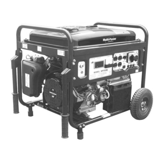
MODEL MP7500E
14 HP Generator
Owner's Manual
DO NOT RETURN TO STORE
Questions? Problems?
Please call our customer help line:
(877) 968-3733
M-F 8-5 CT
02/06
Advertisement
Table of Contents

Summary of Contents for Multi-Power MP7500E
- Page 1 We have made every effort to ensure the accuracy of the information in this manual. Multi-Power reserves the right to change this product at any time without prior notice. This manual may not be reproduced without written consent from Multi-Power.
- Page 2 MODEL MP7500E 14 HP Generator 7500 Surge Watt Output 7000 Rated Watt Output Powerful Enough to Run Essential Appliances During Power Outages 120 and 240 Volt AC Outputs Low Oil Indicator Circuit Breaker for Overload Protection 6.5 Gallon Fuel Tank Capacity...
-
Page 3: Table Of Contents
TABLE OF CONTENTS GENERAL SAFETY PROCEDURES……………………………………………………………... PACKAGE CONTENTS…………………………………………………………………………… GENERATOR COMPONENTS…………………………………………………………………… ASSEMBLY………………………………………………………………………………………… Attach feet…………………………………………………………………………………... Attach handles………………………………………………………………………………. Attach wheels……………………………………………………………………………….. PREPARING THE GENERATOR FOR USE……………………………………………………... Using the Generator for the First Time……………………………………………………... Step 1- Add Oil……………………………………………………………………... Step 2- Add Gasoline……………………………………………………………….. Step 3- Ground the Generator………………………………………………………. Subsequent Use of the Generator…………………………………………………………... -
Page 4: General Safety Procedures
GENERAL SAFETY PROCEDURES Please familiarize yourself with the following safety symbols and words: The safety alert symbol is used with one of the safety words ( DANGER, CAUTION, or WARNING) to alert you to hazards. Please pay attention to these hazard notices both in this manual and on the generator. - Page 5 WARNING: This generator produces powerful voltage, which can result in electrocution. ALWAYS ground the generator before using it (see the “Ground the Generator” portion of the “PREPARING THE GENERATOR FOR USE” section). Generator should only be plugged into electrical devices, either directly or with an extension cord.
- Page 6 In addition to the above safety notices, please familiarize yourself with the safety and hazard markings on the generator.
-
Page 8: Package Contents
PACKAGE CONTENTS Your generator comes with the items listed below. Please check to see that all of the following items are included with your generator. (877) 968-3733 If you are missing components DO NOT RETURN TO STORE, please call M-F 8-5 CT for customer service. ITEM LIST Rubber DC Cord... -
Page 9: Generator Components
GENERATOR COMPONENTS Please familiarize yourself with the locations and functions of the various components and controls of your generator. (1) Fuel Cap- Access to the fuel tank for adding (14) Choke Lever- Adjusts the amount of air let into the fuel. -
Page 10: Assembly
ASSEMBLY In order to best protect the generator wh ile in the package, this product comes with some components disassembled. Please complete the following assembly steps before proceeding to use the generator. For ease of assembly, we recommend attaching the components in the order listed in this manual. If after reading this section, you are unsure about how to perform any of the steps, please call (877)968-3733 M-F 8-5 CT for customer service. -
Page 11: Attach Wheels
The new generator comes with the bolt, bushings, and nut attached to the fram e. To attach the handle, first remove these pieces from the frame. 2. Place one bushing into each hole of the handle bracket. The head (large part) of the bushing should be on the inside of the bracket. - Page 12 Figure 6- wheel installation...
-
Page 13: Preparing The Generator For Use
6. When filling the engine with oil in the future, please refer to this chart. Figure 6- Generator Oil Capacity Model number MP3501 MP3502 MP5500DF MP6000E MP7500E Engine oil capacity 20 fluid oz. 20 fluid oz. 37 fluid oz 37 fluid oz. 37 fluid oz. -
Page 14: Step 2- Add Gasoline
Gas can age in the tank and make it hard to start up the generator in the future. Never store generator for extended periods of time with fuel in the tank. Figure 9- Gas Tank Capacity Model number MP3501 MP3502 MP5500DF MP6000E MP7500E 3.6L Gas tank 15 L (3.96gallons) (6.60gallons) (6.60gallons) (6.60gallons) capacity 0.95gallons... -
Page 15: Subsequent Use Of The Generator
Grounding Wing N ut Figure 10- Grounding nut location Subsequent Use of the Generator If this is not your first time us ing the generator there are still steps you should take to prepare it for operation. IMPORTANT: At this point you should be familiar with the procedures described in the first portion of this section entitled “Using the Generator for the First Time.”... -
Page 16: Step 2- Check The Gas Level
Step 2 – Check the Gas Level Before starting the generator, check to see that there is sufficient gasoline in the gas tank. The fuel gauge on top of the generator will indicate the gas level in the tank. Add gas if necessary according to the steps in the “Adding Gasoline”... -
Page 17: Starting The Generator
STARTING THE GENERATOR Before starting the generator, make sure you have read and performed the steps in the “Preparing the Generator for Use” section of this manual. If you are unsure about how to perform (877) 968-3733 any of the steps in this manual please call M-F 8-5 CT for customer service. -
Page 18: Using The Generator
5000 5500 MP6000E 5500 6000 MP7500E 7000 7500 Figure1 4- generator wattage by model number. The total running wattage requirement of the electrical devices connected to the generator should not exceed the rated wattage of the generator itself. To calculate the total wattage requirement of the electrical devices you wish to conne ct, find the rated (or running) wattage of each device. - Page 19 the generator. Never connect de vices requiring a rated wattage equal to the surge wattage of the generator. tool or appliance rated (running) Watts additional surge Watts electric water heater (40 gal) 4000 hot plate 2500 saw- radial arm 2000 2000 electric stove 1500...
- Page 20 CAUTION: Do not connect 50Hz or 3 -phase loads to the generator . 120V/2 0A AC Duplex 240/ 120VAC Recep tacles Rece ptacle (L14 -30) Figure 16- Receptacles available on the generator CIRCUIT BREAKER The circuit breakers help to prevent the generator fro m electrical overload. If your receptacle short circuits or becomes overloaded by an electrical device or devices with too great a wattage rating, the circuit protector may shut off power to the receptacle.
-
Page 21: Dc Usage
Device Requirements Max. Cord Length (ft) by Wire Gauge Amps Watts (120V) Watts (240 V) #8 wire #10 wire #12 wire #14 wire #16 wire 1000 1200 1800 1200 2400 1800 3600 2400 4800 3000 6000 3600 7200 4800 9600 *NR= not recommended Figure 17- Maximum Extension Cord Lengths by Power Requirement DC Usage... -
Page 22: Maintenance / Care
MAINTENANCE / CARE Proper routine maintenance of your generator will help prolong the life of your machine. Please perform maintenance checks and operati ons according the schedule in figure 1 8. If you have questions about any of the maintenance procedures listed in this manual, please call (877) 968-3733 M-F 8-5 CT CAUTION: Never perform maintenance operations while the generator is running. -
Page 23: Changing/ Adding Oil
When the oil level is low you will need to add oil until the level is sufficient to run the generator. The oil capacity of your generator engine is listed in figure 2 0. MP3501 MP3502 MP5500DF MP6000E MP7500E Model Number Engine oil 20 fluid oz. 20 fluid oz. 37 fluid oz 37 fluid oz 37 fluid oz. -
Page 24: Air Cleaner Maintenance
NOTE: Never dispose of used motor oil in the trash or down a drain. Please call your local recycling center or auto garage to arrange oil disposal. Air Cleaner Maintenance Routine maintenance of the air cleaner helps maintain proper air flow to the carburetor. Check that the air cleaner is free of excessive dirt. -
Page 25: Fuel Filter Cup Cleaning
FUEL VALV E FUEL FILTER C UP Figure 24- Removing the Fuel Filter Cup Spark Plug Maintenance The spark plug is important for proper engine operation. A good spark plug should be intact, free of deposits, and properly gapped. To inspect the spark plug: 1. -
Page 26: Emptying The Gas Tank
Emptying the Gas Tank Before storing the generator for extended periods of time, you should drain the generator of gasoli ne. To drain the generator of gas: 1. Turn the fuel valve to the “off” position. 2. Remove the fuel filter cup (see “ Fuel Filter Cup Cleaning” earlier in this section). 3. -
Page 27: Specifications
SPECIFICATIONS Generator AC Output Model Model Model Model Model MP3501 MP3502 MP5500DF MP6000E MP7500E Rated Wattage 3000 W 3000 W 5000 W 5500W 7000 W Surge Wattage 3500 W 3500 W 5500 W 6000W 7500 W Rated Voltage 120 V... -
Page 28: Troubleshooting
TROUBLESHOOTING 877) 968-3733 IMPORTANT: If trouble persists please call our customer help line at ( M-F 8-5 Central Time. Problem Cause Solution Engine will Engine switch is set to Set engine switch to "on". start "off". Fuel valve is turned to Turn fuel valve to "open"... -
Page 29: Exploded View And Parts List
EXPLODED VIEW AND PARTS LIST... -
Page 30: Parts List
PARTS LIST Item Description Item Description 13hp gasoline engine Gas tank Tubular frame Fuel gauge Left rubber damper Screw M5 10 Right rubber damper Gasket Nut M10 Bolt M6 25 Rubber frame pad Upper tank damper Nut M8 Bolt spacer Air cleaner bracket Lower tank damper M6 14 screw... - Page 31 Item Description Item Description Fuel tank filter Gasket,control pannel EXPLODED VIEW FOR ENGINE...
-
Page 32: Engine Parts List
ENGINE PARTS LIST Description Description Crankcase body M6 Nut Flywheel assembly Air filter base Cooling Fan Air filter cover Starting Cup Air filter core assembly Fan cover Sealing washer M6X10 Bolt Bolt Recoil starter cover Washer Handle Recoil starting cord Oil sensor M6X12 Bolt M6X16 Bolt... -
Page 33: Wiring Diagram
Description Description Piston Muffle washer Piston ring assembly Exhaust washer M6X60 Bolt assembly M8 Nut Lower air baffle Spring washer Air filter gasket Regulating electromagnetic valve WIRING DIAGRAM... - Page 34 NOTES:...
- Page 35 Multi-Power will repair or replace, at its discretion, any part that is proven to be defe ctive in materials or workmanship under normal use during the one (1) year warranty period. Warranty repairs or replacements will be made without charge for parts or labor.
Need help?
Do you have a question about the MP7500E and is the answer not in the manual?
Questions and answers