
Summary of Contents for Ajax TOCCO Toccotron AC
- Page 1 OM-229 158L 2011−11 Processes Induction Heating Description Induction Heating Power Source Toccotron AC Visit our website at File: Induction Heating www.AjaxTocco.com...
-
Page 3: Table Of Contents
TABLE OF CONTENTS SECTION 1 − SAFETY PRECAUTIONS − READ BEFORE USING ....... . . 1-1. - Page 4 TABLE OF CONTENTS SECTION 7 − MAINTENANCE ..............7-1.
-
Page 5: Section 1 − Safety Precautions − Read Before Using
SECTION 1 − SAFETY PRECAUTIONS − READ BEFORE USING ihom _2010−03 Protect yourself and others from injury — read and follow these precautions. 1-1. Symbol Usage DANGER! − Indicates a hazardous situation which, if Indicates special instructions. not avoided, will result in death or serious injury. The possible hazards are shown in the adjoining symbols or explained in the text. -
Page 6: Additional Symbols For Installation, Operation, And Maintenance
FIRE OR EXPLOSION hazard. INDUCTION HEATING can burn. D Do not overheat parts. D Do not touch hot parts bare-handed. D Watch for fire; keep extinguisher nearby. D Allow cooling period before handling parts or equipment. D Keep flammables away from work area. D Do not touch or handle induction head/coil Do not locate unit on, over, or near combustible surfaces. -
Page 7: California Proposition 65 Warnings
1-4. California Proposition 65 Warnings For Gasoline Engines: Welding or cutting equipment produces fumes or gases which contain chemicals known to the State of California to Engine exhaust contains chemicals known to the State of cause birth defects and, in some cases, cancer. (California California to cause cancer, birth defects, or other reproduc- Health &... -
Page 8: Section 2 − Consignes De Sécurité − Lire Avant Utilisation
SECTION 2 − CONSIGNES DE SÉCURITÉ − LIRE AVANT UTILISATION ihom _2010−03fre Se protéger, ainsi que toute autre personne travaillant sur les lieux, contre les étincelles et le métal chaud. 2-1. Signification des symboles DANGER! − Indique une situation dangereuse qui si on Indique des instructions spécifiques. -
Page 9: Dangers Supplémentaires En Relation Avec L'installation, Le Fonctionnement Et La Maintenance
flux, les métaux, les consommables, les revêtements, les net- Ne pas placer l’appareil sur, au-dessus ou à proximité de surfaces toyants et les dégraisseurs. inflammables. Travailler dans un espace fermé seulement s’il est bien ventilé ou en Ne pas installer l’appareil à proximité de produits inflammables. portant un respirateur. -
Page 10: Proposition Californienne 65 Avertissements
Effectuer régulièrement le contrôle et l’entretien de l’installation. LE RAYONNEMENT HAUTE FRÉ- Maintenir soigneusement fermés les portes et les panneaux des QUENCE (HF) risque de provoquer sources de haute fréquence. des interférences. LIRE LES INSTRUCTIONS. D Le rayonnement haute fréquence (HF) peut provoquer des interférences avec les équipe- D Lire et appliquer les instructions sur les ments de radio-navigation et de communication,... -
Page 11: Informations Relatives Aux Cem
2-6. Informations relatives aux CEM Le courant électrique qui traverse tout conducteur génère des champs 4. Maintenir la tête et le torse aussi loin que possible du matériel du circuit de soudage. électromagnétiques (CEM) à certains endroits. Le courant de soudage crée un CEM autour du circuit et du matériel de soudage. -
Page 12: Section 3 − Definitions
SECTION 3 − DEFINITIONS 3-1. Warning Label Definitions Warning! Watch Out! There are possible hazards as shown by the symbols. Electric shock from wiring can kill. 1.1 Wear dry insulating gloves. Do not wear wet or damaged gloves. 1.2 Disconnect input plug or power before working on machine. - Page 13 3-1. Warning Label Definitions (Continued) Warning! Watch Out! There are possible hazards as shown by the symbols. Electric shock from wiring can kill. Overuse can cause overheating. Follow rated duty cycle. Disconnect input plug or power before working on machine. Become trained and read the instructions before working on the machine.
-
Page 14: Symbols And Definitions
3-2. Symbols And Definitions Some symbols are found only on CE products. Amperes Volts Alternating Current Duty Cycle Degree Of Hertz Circuit Protector Output Protection Increase Line Connection Primary Current Rated Current Three Phase Static Frequency Con- Primary Voltage Load Voltage Read Instructions verter-Transform- er-Frequency Con-... -
Page 15: Section 4 − Installation
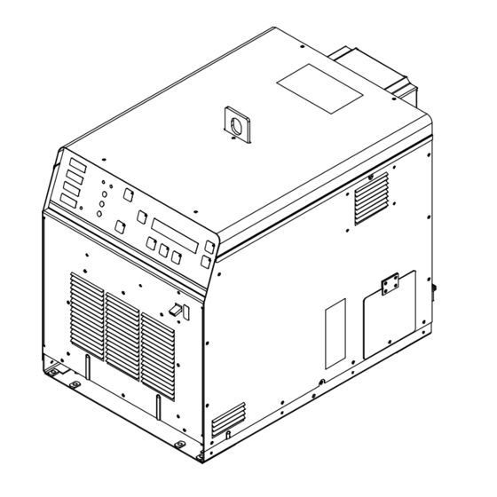
SECTION 4 − INSTALLATION 4-1. Serial Number and Rating Label Location The serial number and rating information for the power source is located on the front of the machine. Use the rating labels to determine input power requirements and/or rated output. For future reference, write serial number in space provided on back cover of this manual. 4-2. -
Page 16: Tipping
4-4. Tipping Do not move or operate unit where it could tip. 4-5. Electrical Service Guide Failure to follow these electrical service guide recommendations could create an electric shock or fire hazard. These recommenda- tions are for a dedicated circuit sized for the rated output and duty cycle of the welding power source. In dedicated circuit installations, the National Electrical Code (NEC) allows the receptacle or conductor rating to be less than the rating of the circuit protection device. -
Page 17: Connecting 3-Phase Input Power For 460/575 Volt Models
4-6. Connecting 3-Phase Input Power For 460/575 Volt Models Installation must meet all National and Local Codes − have only quali- fied persons make this installation. Disconnect and lockout/tagout in- GND/PE Earth Ground put power before connecting input conductors from unit. Make input power connections to the welding power source first. -
Page 18: Connecting 3-Phase Input Power For 400/460 Volt Models
4-7. Connecting 3-Phase Input Power For 400/460 Volt Models Tools Needed: 3/8 in. = GND/PE Earth Ground Ref. 804 430-A / Ref. 804 598-A Select size and length of conductors using Disconnect Device Input Power Connec- Installation must meet all National and Section 4-5. -
Page 19: Power Source Output Connections
4-8. Power Source Output Connections 1. Output Bus Bars Use supplied 1/4-20 nuts to make electrical connections to the output bus bars as required by the specific application. 804 597-A OM-229 158 Page 15... -
Page 20: Remote 14 Receptacle Rc14 Information And Connections
4-9. Remote 14 Receptacle RC14 Information and Connections 1. Plug 2. Threaded Collar 3. Keyway 4. Remote 14 Receptacle RC14 (See Section 4-10) To connect to receptacle, align key- way, insert plug and tighten threaded collar. C L N 804 597-A 4-10. -
Page 21: I/O Receptacle Rc13 Information And Connections
4-11. I/O Receptacle RC13 Information And Connections 1. Plug 2. Threaded Collar 3. I/O Receptacle RC13 (See Section 4-12) To connect to receptacle, insert plug and tighten threaded collar. 804 597-A 4-12. I/O Receptacle RC13 Socket Information Socket No. Socket Information Incycle Common Incycle Normally Closed Incycle Normally Open... -
Page 22: Secondary Insulation Protection
4-13. Secondary Insulation Protection Connect ground lead(s) between the workpiece and power source to provide proper secondary insulation protection from a short in the output circuit. Secondary insulation protection circuitry automatically shuts down the power source output if a potentially hazardous condition exists... -
Page 23: 115 Volt Ac Duplex Receptacle And Supplementary Protector
4-14. 115 Volt AC Duplex Receptacle And Supplementary Protector 1. 115 VAC 2.5 A Single-Phase AC Receptacle RC1 2. Supplementary Protector CB1 (2.5 A) The receptacle supplies nominal 115 volts AC auxiliary power. Maximum output from receptacle is 2.5 am- peres. -
Page 24: Section 5 − Components And Controls
SECTION 5 − COMPONENTS AND CONTROLS 5-1. Controls 804 599-A 6. Degrees C LED 13. Cursor Button When a control panel button is pushed Use button to move selection cursor in the Power source temperature display in de- the yellow lamp lights to indicate ac- 4 x 40 LCD display (item 14.). -
Page 25: Section 6 − Setup And Operation
1/94 6-2. System Description The Toccotron AC is intelligent to the point that it will automatically adjust output power levels if internal system operating parameters or internal temper- atures reach or exceed specific set limits (see Section 9). 6-3. Power Source/System Setup... - Page 26 Possible selections Setup 2: System Lock − Yes/No Control Mode − Timed / Remote / Manual Command − Power / Voltage / Current Max KW: 1−35 Degree Units − F / C Backlight − Yes/No Isolation Detect − Yes/No Time Resolution − press the Increase or Decrease button to select the desired time resolution.
-
Page 27: Programming
Backlight − press the Increase or Decrease button to turn LCD display backlight On or Off. The factory default is On. Isolation Detect− press the Increase or Decrease button to enable or disable this feature. The factory default is Yes. All parameters in System Setup are considered global, and any changes to the system set-up parameters will apply to all programs. -
Page 28: 6-4-3.Manual Control
Mode..: Remote Power..: 0.0 KW Run Time:>00:03:00 Current: Voltage: Frequency: 4.5 KHz Time is the only parameter that can be set. The values are 0 − 99:59:59 or infinity. 6-4-3. Manual Control Manual control allows programming of a specific power level for a specific period of time. When this process is selected, the following screen appears on the display: Mode..: Manual Power..:... -
Page 29: 6-5-1.Time Based Control
6-5-1. Time Based Control Mode...: Timed Segment KWS: Program: 1 Segment: 0 x1 Type...: End Power..: 0.0 KW SegmentTime: 00:00:00 Mode displays the control mode. Also displayed are the present program number, program segment, KW seconds, Segment type, current power level and elapsed time of the current segment. -
Page 30: Real-Time Operation
Each time the unit is first turned On it initiates a system check routine that includes verification of communication between circuit boards and checking for output isolation faults. During this check routine, all displays and LEDs illuminate and the following screen appears on the display: TOCCOtron AC Firmware Revision OEM 0.52 Copyright (c) 2006 X.XX indicates the firmware revision number installed in the unit. -
Page 31: Section 7 − Maintenance
Press the Run button to resume program operation and the yellow indicator LED will illuminate. Press the Stop button to end the program. SECTION 7 − MAINTENANCE 7-1. Routine Maintenance Disconnect power Maintain more often before maintaining. during severe conditions. n = Check Z = Change ~ = Clean... -
Page 32: Section 8 − Safety Precautions For Servicing
SECTION 8 − SAFETY PRECAUTIONS FOR SERVICING Protect yourself and others from injury — read and follow these precautions. 8-1. Symbol Usage OM-___ - Date, safety_ihtm 2010−03 DANGER! − Indicates a hazardous situation which, if Indicates special instructions. not avoided, will result in death or serious injury. The possible hazards are shown in the adjoining symbols or explained in the text. -
Page 33: California Proposition 65 Warnings
MOVING PARTS can injure. H.F. RADIATION can cause interference. D High-frequency (H.F.) can interfere with radio D Keep away from moving parts such as fans. navigation, safety services, computers, and D Have only qualified persons remove doors, communications equipment. panels, covers, or guards for maintenance and troubleshooting as necessary. -
Page 34: Section 9 − Diagnostics & Troubleshooting
SECTION 9 − DIAGNOSTICS & TROUBLESHOOTING The Toccotron AC power source has on-board capabilities to aid in troubleshooting problems should any conditions occur during operation. This troubleshooting capability consists of the Fault LED, Limit LED, and message screens that appear on the front panel LCD display. -
Page 35: Limit Condition Codes
Pressing the Decrease button will acknowledge the limit and continue operation with the existing setup. In the acknowledge state, the yellow Limit LED will stop flashing and remain on continuously. The LCD display will revert to an active screen once the Program button, Run Status button, or Parameters button is pressed. -
Page 36: System Diagnostic Screens
Fault Condition Additional Information F62: Isolation Fault Check for exposed conductor Clean for moisture on cables F63:Line Voltage Fault Check line voltage F64: Power Source Overtemp Fault Verify power source vents and wind tunnel are unobstructed F65: Current Source Fault Service required F66: Under Frequency Fault Check for loose or open connections... - Page 37 VLnA-B − This is the approximate phase to phase line voltage between phases A and B. VLnB-C − This is the approximate phase to phase line voltage between phases B and C. VLnC-A − This is the approximate phase to phase line voltage between phases C and A. VBus −...
-
Page 38: Removing Wrapper And Measuring Input Capacitor Voltage
9-7. Removing Wrapper and Measuring Input Capacitor Voltage 900 Volts dc can be present on the capacitor bus and significant DC voltage can remain on capacitors after unit is Off. Always check the Tools Needed: voltage on inverter assembly as shown to be sure the input 5/16, 3/8 in capacitors have discharged before working on unit. -
Page 39: Blowing Out Inside Of Unit
9-8. Blowing Out Inside Of Unit Turn Off welding power source and disconnect input power. Remove wrapper and be sure input capacitors are discharged. Blow out inside of unit. Blow out fan motors in right side panel and front panel. 804 601-B OM-229 158 Page 35... -
Page 40: Section 10 − Electrical Diagram
SECTION 10 − ELECTRICAL DIAGRAM Figure 10-1. Circuit Diagram OM-229 158 Page 36... - Page 41 219 029-B OM-229 158 Page 37...
-
Page 42: Section 11 − Parts List
SECTION 11 − PARTS LIST Hardware is common and not available unless listed. See Figure 11-3 See Figure 11-2 804 601-B Figure 11-1. Wrappers Item Dia. Part Mkgs. Description Quantity Figure 11-1. Wrappers ....+217 470 PANEL, side RH . - Page 43 Hardware is common and not available unless listed. 804 602-B Figure 11-2. Front Panel Item Dia. Part Mkgs. Description Quantity Figure 11-2. Front Panel ....217 323 PANEL, front .
- Page 44 ... . . 229 153 INSULATOR, output TOCCOTRON AC ......
- Page 45 Hardware is common and not available unless listed. 804 221-D Figure 11-4. Base w/Components Item Dia. Part Mkgs. Description Quantity Figure 11-4. Base w/Components ....217 328 FRAME, lifting .
- Page 46 Hardware is common and not available unless listed. 804 604-B Figure 11-5. Top Windtunnel Item Dia. Part Mkgs. Description Quantity Figure 11-5. Top Windtunnel ....218 424 WINDTUNNEL, top .
- Page 47 Hardware is common and not available unless listed. 804 605-B Figure 11-6. Right Windtunnel Item Dia. Part Mkgs. Description Quantity Figure 11-6. Right Windtunnel ....216 630 WINDTUNNEL, RH .
- Page 48 Item Dia. Part Mkgs. Description Quantity Figure 11-6. Right Windtunnel (Continued) ....229 728 STRAP, connecting ..........
- Page 49 Hardware is common and not available unless listed. 804 225-A Figure 11-7. Left Windtunnel Item Dia. Part Mkgs. Description Quantity Figure 11-7. Left Windtunnel ....216 631 WINDTUNNEL, LH .
- Page 50 Item Dia. Part Mkgs. Description Quantity Figure 11-7. Left Windtunnel (Continued) ..PLG16, 121,122 . . . 131 054 HOUSING RCPT+SKTS,(SERVICE KIT) ......
-
Page 51: Warranty
Warranty Effective January 1, 2011 (Equipment with a serial number preface of MB or newer) This limited warranty supersedes all previous manufacturers 90 Days — Parts warranties and is exclusive with no other guarantees or Accessory (Kits) warranties expressed or implied. Canvas Covers Induction Heating Coils and Blankets, Cables, and LIMITED WARRANTY −... - Page 52 Owner’s Record Please complete and retain with your personal records. Model Name Serial/Style Number Purchase Date (Date which equipment was delivered to original customer.) Distributor Address City State Resources Available Always provide Model Name and Serial/Style Number. Contact your Distributor for: Welding Supplies and Consumables Options and Accessories Personal Safety Equipment...
Need help?
Do you have a question about the Toccotron AC and is the answer not in the manual?
Questions and answers
On the Ajax tocco magnethermic system it’s says fault protect and nothing else? What is the issue?
On the Ajax Rocco system it’s says fault protect ? So what is the issue?