
Subscribe to Our Youtube Channel
Related Manuals for PowCon SGS 30A


Summary of Contents for PowCon SGS 30A
- Page 1 OM-183 304A September 1998 Processes MIG (GMAW) Welding Description Feeder Gun SGS 30A...
-
Page 3: Table Of Contents
TABLE OF CONTENTS SECTION 1 − SAFETY PRECAUTIONS FOR ARC WELDING ....... 1-1. - Page 5 This information is provided for units with CE certification (see rating label on unit). PowCon Incorporated Manufacturer’s Name: 8123 Miralani Drive Manufacturer’s Address: San Diego, CA 92126 USA SGS 30A Declares that the product: conforms to the following Directives and Standards: Directives Low Voltage Directive: 73/23/EEC Electromagnetic Compatibility (EMC) Directive: 89/336/EEC...
-
Page 7: Section 1 − Safety Precautions For Arc Welding
SECTION 1 − SAFETY PRECAUTIONS FOR ARC WELDING safety_som1 4/95 OM-183 304 − 11/96 1-1. Symbol Usage Y Marks a special safety message. Means Warning! Watch Out! There are possible hazards with this procedure! The possible hazards are shown in the adjoining symbols. Means NOTE;... -
Page 8: Additional Installation, Operation, And Maintenance Hazards
CYLINDERS can explode if damaged. 4. Never drape a welding torch over a gas cylinder. 5. Never allow a welding electrode to touch any cylinder. Shielding gas cylinders contain gas under high 6. Never weld on a pressurized cylinder − explosion will result. pressure. -
Page 9: Principal Safety Standards
OVERUSE can cause OVERHEATED SIGNIFICANT DC VOLTAGE exists after EQUIPMENT. removal of input power on inverters. 1. Allow cooling period. 1. Turn Off inverter, disconnect input power, and 2. Reduce current or reduce duty cycle before discharge input capacitors according starting to weld again. -
Page 10: Section 1 − Consignes De Sécurité Pour Le
SECTION 1 − CONSIGNES DE SÉCURITÉ POUR LE SOUDAGE À L’ARC safety_som_cfr 4/95 1-1. Signification des symboles Signifie Mise en garde! Attention! Ce mode opératoire peut Y Indique un message de sécurité spécial. présenter des dangers! Les dangers possibles sont indiqués par Signifie NOTA;... -
Page 11: Autres Dangers Relatifs À L'installation, L'utilisation Et L'entretien
VAPEURS FUMÉES 5. Ne travailler dans un espace confiné que s’il est bien ventilé, ou en portant un appareil respiratoire à adduction d’air pur. Demander à peuvent être dangereuses pour la un observateur ayant reçu la bonne formation de toujours se tenir santé. -
Page 12: Principales Normes De Sécurité
LES CHAMPS MAGNÉTIQUES PRO- L’ÉLECTRICITÉ STATIQUE peut en- DUITS PAR LES COURANTS ÉLEVÉS dommager les pièces des circuits impri- peuvent nuire au fonctionnement du més. stimulateur cardiaque 1. Mettre un bracelet antistatique AVANT de manipu- ler les cartes de circuits imprimés ou les pièces. 1. -
Page 13: Informations Sur Les Champs Électromagnétiques
1-5. Informations sur les champs électromagnétiques NOTA Données sur le soudage et sur les effets des champs électri- au sujet des risques éventuels, ni proposer des méthodes scientifi- ques précises pour réduire ces risques ou pour les éviter.» ques et magnétiques basse fréquence. Pour réduire l’intensité... -
Page 14: Section 2 − Definitions
Section 4-1. = 30V = 1A IP 23 = 100V = 200A X 100% PowCon Incorporated, San Diego, CA USA S-182 589 S-182 589 2-2. Symbols And Definitions NOTE Some symbols are found only on CE products. Primary Voltage... -
Page 15: Section 3 − Installation
SECTION 3 − INSTALLATION 3-1. Specifications Approximate Weld Wire Diameter Cooling Maximum Overall Wire Feed Circuit IP Rating Weight Range Method Spool Size Dimensions Range Rating .025 Thru 1/16 in 2.9 lb 100 Volts, Length: 15-3/8 in (0.6 Thru 1.6 mm) (1.3 kg) Gun 200 Amperes, (390 mm) -
Page 16: Installing Wire Spool And Threading Welding Wire
3-4. Installing Wire Spool And Threading Welding Wire Top Cover Canister Canister Cover Thumbscrew (Canister Cover) Loosen thumbscrew and remove cover. Wire Spool Loosen wire from spool, cut off bent wire, and pull 6 in (150 mm) of wire off spool. Pressure Roll Assembly Lift arm and open pressure roll assembly. -
Page 17: Connecting To 24 Volt Weld Control
3-6. Connecting To 24 Volt Weld Control Gas Hose 10 ft (3 m) Gas Hose With 5/8 in Adapter Fitting Connect fitting to gun/feeder gas hose and remaining end to regula- tor/flowmeter (see Section 3-7). 24 Volt Weld Control Trigger Control Cord Insert plug into receptacle, and tighten threaded collar. -
Page 18: Installing Gas Supply
3-7. Installing Gas Supply Obtain gas cylinder and chain to running gear, wall, or other station- ary support so cylinder cannot fall and break off valve. Cylinder Valve Remove cap, stand to side of valve, and open valve slightly. Gas flow blows dust and dirt from valve. -
Page 19: Adjusting Drive Roll And Spool Brake Pressure
3-8. Adjusting Drive Roll And Spool Brake Pressure Top Cover Canister Cover Thumbscrew Loosen thumbscrew and remove cover. Spool Cut welding wire off at contact tip. Retract wire onto spool and secure. Spool Brake Thumbnut Grasp spool in one hand and turn while adjusting spool brake thumb- nut. -
Page 20: Section 4 − Operation
SECTION 4 − OPERATION 4-1. Controls Trigger Press trigger to energize welding power source contactor (if applica- ble), start shielding gas flow, and begin wire feed. For shielding gas preflow and post- flow, lightly press trigger before and after welding. Trigger Hold Button Use button to continually feed wire without holding down the trigger. -
Page 21: Section 5 − Maintenance & Troubleshooting
SECTION 5 − MAINTENANCE & TROUBLESHOOTING 5-1. Routine Maintenance Y Disconnect power Maintain more often before maintaining. during severe conditions. 3 Months Clean Replace Replace Damaged Or Damage Tighten Unreadable Gas Hose Weld Labels Terminals Repair Or Replace Cracked Cables And Cords 6 Months Blow Out Or... -
Page 22: Gun Drive Assembly Maintenance
5-3. Gun Drive Assembly Maintenance Retract wire onto spool. Setscrew Current Pick-Up Tab This tab helps prevent burnback caused by welding arcs inside the contact tip. This tab may be re- moved to provide an insulated drive roll. (If tab is removed, a smaller di- ameter contact tip is recom- mended. -
Page 23: Replacing Canister Inlet Guide
5-4. Replacing Canister Inlet Guide Top Cover Pressure Roll Assembly Cut off welding wire where it enters pressure roll assembly area. Nozzle Pull wire out nozzle. Thumbscrew Canister Cover Loosen thumbscrew and remove cover. Wire Spool Spool Brake Thumbnut Loosen thumbnut, retract wire onto spool, secure, and remove spool. -
Page 24: Replacing Contact Tip Adapter
5-6. Replacing Contact Tip Adapter Barrel Extension Remove as shown. Contact Tip Compression Nut To remove, see Section 5-2. Liner Contact Tip Adapter O-Ring Head Tube Head Tube Setscrew Loosen setscrews and remove adapter. Install new o-ring and adapter, and tighten setscrews. -
Page 25: Section 6 − Electrical Diagrams
SECTION 6 − ELECTRICAL DIAGRAMS 138 956-B Figure 6-1. Circuit Diagram For Gun/Feeder OM-222 Page 19... - Page 26 Notes OM-183 304 Page 20...
-
Page 27: Section 7 − Parts List
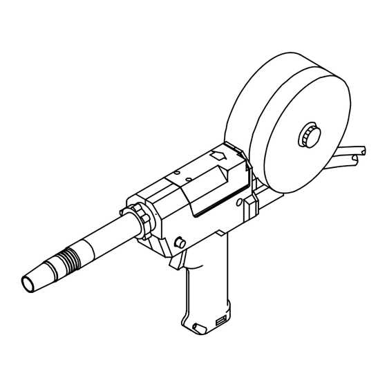
SECTION 7 − PARTS LIST Hardware is common and not available unless listed. 143 116-J Figure 7-1. Complete Assembly OM-183 304 Page 21... - Page 28 Item Dia. Part Mkgs. Description Quantity Figure 7-1. Complete Assembly ....133 479 COVER ............
- Page 29 Item Dia. Part Mkgs. Description Quantity Figure 7-1. Complete Assembly (Continued) ....155 565 SCREW, thumb ..........
-
Page 30: Options And Accessories
(1.2 and 1.6 mm) wire (1.2 and 1.6 mm) wire For 10 in. Barrel (#144 854) .030 and .035 in. *Note: Uses standard SGS 30A contact (0.8 and 0.9 mm) wire tips. (Refer to SGS 30A Gun Consumables chart for contact tips.) (#144 855) .047 and 1/16 in. - Page 31 This claim is valid for 60 days thereafter. of the time and place of delivery by PowCon. The This warranty is valid for all equipment manufactured limited warranty is for the periods indicated below, by PowCon after March 25, 1996.
- Page 32 Owner’s Record Please complete and retain with your personal records. Model Name Serial/Style Number Purchase Date (Date which equipment was delivered to original customer.) Distributor Address City State Resources Available Always provide Model Name and Serial/Style Number. Welding Supplies and Consumables Contact your Distributor for: Options and Accessories Personal Safety Equipment...
Need help?
Do you have a question about the SGS 30A and is the answer not in the manual?
Questions and answers