Table of Contents
Advertisement
Advertisement
Table of Contents

Subscribe to Our Youtube Channel
Related Manuals for Lenovo IdeaCentre A730


Summary of Contents for Lenovo IdeaCentre A730
- Page 1 IdeaCentre A730 Hardware Maintenance Manual Machine Types: 10123/F0A0 [A730]...
- Page 3 IdeaCentre A730 Hardware Maintenance Manual Machine Types: 10123/F0A0 [A730]...
- Page 4 Second Edition (June 2013)6th © Copyright Lenovo 2013. LIMITED AND RESTRICTED RIGHTS NOTICE: If data or software are delivered pursuant a General Services Administration “GSA” contract, use, reproduction, or disclosure is subject to restrictions set forth in Contract No. GS-35F-05925...
-
Page 5: Table Of Contents
Selecting a startup device ..Replacing the power switch board ..Exiting the Lenovo BIOS Setup Utility program . . Replacing the Bluetooth module.. - Page 6 IdeaCentre A730Hardware Maintenance Manual...
-
Page 7: Chapter 1. About This Manual
Chapter 1. About this manual This manual contains service and reference information for IdeaCentre A730 computers listed on the cover. It is intended only for trained servicers who are familiar with Lenovo computer products. Before servicing a Lenovo product, be sure to read the Safety Information. - Page 8 IdeaCentre A730Hardware Maintenance Manual...
-
Page 9: Chapter 2. Safety Information
Electrical current from power, telephone, and communication cables can be hazardous. To avoid personal injury or equipment damage, disconnect any attached power cords, telecommunication cables, network cables, and modem cables before you open the computer covers, unless instructed otherwise in the installation and configuration procedures. © Copyright Lenovo 2013... - Page 10 Observe the following rules when working on electrical equipment. Important: Use only approved tools and test equipment. Some hand tools have handles covered with a soft material that does not insulate you when working with live electrical currents. Many customers have rubber floor mats near their equipment that contain small conductive fibers to decrease electrostatic discharge.
-
Page 11: Safety Inspection Guide
– Switch off power. – Send another person to get medical aid. Safety inspection guide The intent of this inspection guide is to assist you in identifying potential hazards posed by these products. Each computer, as it was designed and built, had required safety items installed to protect users and service personnel from injury. -
Page 12: Grounding Requirements
• Keep the parts in protective packages until they are inserted into the product. • Avoid contact with other people while handling the part. • Wear a grounded wrist strap against your skin to eliminate static on your body. • Prevent the part from touching your clothing. Most clothing is insulative and retains a charge even when you are wearing a wrist strap. - Page 13 To Connect To Disconnect 1. Turn everything OFF. 1. Turn everything OFF. 2. First, attach all cables to devices. 2. First, remove power cords from outlets. 3. Attach signal cables to connectors. 3. Remove signal cables from connectors. 4. Attach power cords to outlet. 4.
- Page 14 ≥18 kg (37 lbs) ≥32 kg (70.5 lbs) ≥55 kg (121.2 lbs) CAUTION: Use safe practices when lifting. CAUTION: The power control button on the device and the power switch on the power supply do not turn off the electrical current supplied to the device. The device also might have more than one power cord.
-
Page 15: Chapter 3. General Information
This chapter provides general information that applies to all computer models covered by this manual. Specifications This section lists the physical specifications for your computer. This section lists the physical specifications for your computer. Type IdeaCentre A730 This section lists the physical specifications. Environment Air temperature: Operating: 10°... - Page 16 IdeaCentre A730Hardware Maintenance Manual...
-
Page 17: Chapter 4. General Checkout
• If the computer displays a POST error, go to “POST error codes”. • If the computer hangs and no error is displayed, continue at step 7. 7. If the test stops and you cannot continue, replace the last device tested. © Copyright Lenovo 2013... - Page 18 IdeaCentre A730Hardware Maintenance Manual...
-
Page 19: Chapter 5. Using The Setup Utility
1. If your computer is already on when you start this procedure, shut down the operating system and turn off the computer. 2. Press and hold the F1 key then turn on the computer. When the Lenovo BIOS Setup Utility program is displayed, release the F1 key. - Page 20 5. Select Save changes and Exit from the menu. Power-On Password When a Power-On Password is set, you cannot start the Lenovo BIOS Setup Utility program until a valid password is typed from the keyboard. Setting, changing, or deleting a Power-On Password Note: A password can be any combination of letters and numbers up to 16 characters (a-z and 0-9).
-
Page 21: Enabling Or Disabling A Device
To set a Power-On Password, do the following: 1. Start the Lenovo BIOS Setup Utility program (See ”Starting the Lenovo BIOS Setup Utility program” on page 13.) 2. From the Security menu, select Set Power-On Password and press the Enter key. -
Page 22: Selecting A Startup Device
Selecting or changing the startup device sequence To view or permanently change the configured startup device sequence, do the following: 1. Start the Lenovo BIOS Setup Utility program (see “Starting the Lenovo BIOS Setup Utility program” on page 13). 2. From the Lenovo BIOS Setup Utility program main menu, select the Startup option. -
Page 23: Exiting The Lenovo Bios Setup Utility Program
Exiting the Lenovo BIOS Setup Utility program After you finish viewing or changing settings, press the Esc key to return to the Lenovo BIOS Setup Utility program main menu. You might have to press the Esc key several times. Do one of the following: •... - Page 24 IdeaCentre A730Hardware Maintenance Manual...
-
Page 25: Chapter 6. Symptom-To-Fru Index
Check that the following are properly installed: Reseat connectors • Power Cord • On/Off Switch connector • System Board Power Supply connectors • Microprocessor connections Check the power cord. Power Cord Check the power-on switch. Power-on Switch © Copyright Lenovo 2013... -
Page 26: Post Error Codes
POST error codes Each time you turn the computer on, it performs a series of tests to check that the system is operating correctly and that certain options are set. This series of tests is called the Power-On Self-Test, or POST. POST does the following: •... -
Page 27: Chapter 7. Locating Connectors, Controls And Components
3. Power indicator 11. Novo Vision button 4. Hard disk drive indicator 12. Volume down 5. Bluetooth status indicator 13. Volume up 6. WIFI status indicator 14. Brightness down 7. HDMI-in indicator 15. Brightness up 8. Built-in speakers © Copyright Lenovo 2013... - Page 28 Left and right view The following illustration shows the location of connectors, controls and components on the left and right side of the computer. 1. Air vents 6. Optical drive 2. USB 3.0 connector 7. B-CAS card slot (Japan models only) 3.
- Page 29 Rear view The following illustration shows the location of connectors and components on the rear of the computer. 1. TV tuner connector (selected models only) 5. USB 2.0 connectors (2) 2. Headphone connector 6. Power connector 3. Microphone connector 7. Ethernet connector (RJ45) 4.
- Page 30 Hardware components The following illustration shows the components that make up your computer. 1. System fan 17. Bluetooth module 2. Scalar board 18. Power switch board 3. Hard disk drive bracket 19. Front function board 4. Hard disk drive 20. Battery 5.
- Page 31 Identifying parts on the motherboard The motherboard (sometimes called the planar or system board) is the main circuit board in your computer. It provides basic computing functions and supports a variety of devices that are factory-installed or that you can install later. The following illustration shows the location of connectors and components on the front of the motherboard.
- Page 32 The following illustration shows the location of connectors and components on the back of the motherboard. 23. TV-Tuner card connector 24. Battery IdeaCentre A730Hardware Maintenance Manual...
- Page 33 Identifying parts on the back of the LED panel The following illustration shows the components and controls on the back of LED panel. 1. Bluetooth module 5. Front function board 2. WLAN card 6. Converter board 3. Camera 7. Scalar board 4.
- Page 34 IdeaCentre A730Hardware Maintenance Manual...
-
Page 35: Chapter 8. Replacing Hardware
Attention: Do not remove the computer cover or attempt any repair before reading the “Important safety information” in the Safety and Warranty Guide that was included with your computer. To obtain copies of the Safety and Warranty Guide, go to the Support Web site at: http://consumersupport.lenovo.com. Note: Use only parts provided by Lenovo. -
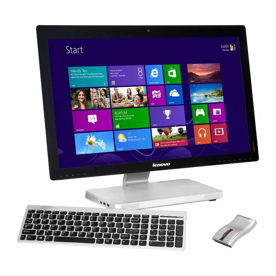
Page 36: Replacing The Keyboard And Mouse
Replacing the keyboard and mouse Attention: Turn off the computer and wait 3 to 5 minutes to let it cool down before removing the cover. To replace the keyboard and mouse Step 1. Remove any media (disks, CDs, DVDs or memory cards) from the drives, shut down the operating system, and turn off the computer and all attached devices. -
Page 37: Removing The Base Cover
Note: Turn off the computer and wait 3 to 5 minutes to let it cool down before removing the cover. Note: It may be helpful to place the computer face-down on a soft flat surface for this procedure. Lenovo recommends that you use a blanket, towel, or other soft cloth to protect the computer screen from scratches or other damage. -
Page 38: Replacing The Hard Disk Drive
Step 5. Return the computer to an upright position, then lift the base cover up and slide it out as shown. Step 6. To reattach the base cover: Line up the base cover with the base, slide it back and snap it into position. Place the computer face-down on a soft flat surface, then secure the base cover to the base with the 7 screws. - Page 39 Step 5. Remove the 2 screws that secure the hard disk drive to the motherboard. Step 6. Disconnect the data and power cable from the hard disk drive. Step 7. Slide the hard disk drive and rubber out of the bay as shown. Step 8.
-
Page 40: Replacing A Memory Module
Secure the new hard disk drive to motherboard with the 2 screws. Connect the data and power cable to the new hard disk drive and motherboard. Step 10. Reattach the base cover and secure it with the screws. Replacing a memory module Attention: Turn off the computer and wait 3 to 5 minutes to let it cool down before removing the cover. -
Page 41: Replacing The Heat-Sink
Step 5. Remove the 3 screws that secure the system fan to the heat-sink. Step 6. Disconnect the power cable from the motherboard. Step 7. Lift the system fan up to remove it. Step 8. Line up the new system fan, then secure it to the heat-sink and connect the new power cable to the motherboard. -
Page 42: Replacing The Cpu
Step 7. Remove the heat-sink by lifting it up. Attention: Place the heat-sink upside down on a flat surface to prevent thermal grease from contaminating other components. Attention: Use an alcohol pad to wipe the thermal grease off the heat-sink and CPU. Step 8. - Page 43 Step 8. Lift the microprocessor straight up and out of the socket. Attention: Do not touch the gold contacts on the bottom of the microprocessor. When handling the microprocessor, touch only the sides. Note: Do not drop anything onto the microprocessor socket while it is exposed. The socket pins must be kept as clean as possible.
-
Page 44: Replacing The Optical Drive
Step 11. Lower the microprocessor straight down into its socket on the motherboard. Step 12. To secure the microprocessor in the socket, close the microprocessor retainer and lock it into position with the small handle. Step 13. Use a thermal grease syringe to place 5 drops of grease on the top of the microprocessor. Each drop of grease should be 0.03ml (3 tick marks on the grease syringe). - Page 45 Step 6. Remove the 3 screws that secure the optical drive to the motherboard and lift it up to remove it. Step 7. Remove the 5 screws that secure the optical drive to the bracket and disconnect the data cable from the optical drive.
-
Page 46: Replacing The Solid State Disk
Replacing the solid state disk Note: Turn off the computer and wait 3 to 5 minutes to let it cool down before removing the cover. To replace the solid state disk Step 1. Remove any media (disks, CDs, DVDs, or memory cards) from the drives, shut down the operating system, and turn off the computer and all attached devices. -
Page 47: Replacing The Motherboard
Step 6. Lift up the optical drive eject board to remove it. Step 7. To install the new optical drive eject board: Connect the new optical drive eject board to the motherboard. Secure the new optical drive eject board to the motherboard with the 2 screws. Step 8. - Page 48 Step 14. Remove the 8 screws that secure the motherboard to the chassis and slide it out as shown. Step 15. Remove the 2 screws that secure the TV-Tuner card to the motherboard. Step 16. Disconnect the antenna cable(s) from the TV-Tuner card. Step 17.
-
Page 49: Replacing The Speaker System
Step 18. Use a flat head screwdriver as a lever to prise out the battery as shown. Step 19. To install the new motherboard: Insert the battery (CR2032) into the socket with the side labeled “+” facing up, and press the battery into place. - Page 50 Step 10. Remove the 8 screws that secure the motherboard to the chassis and slide it out as shown. Step 11. Remove the 4 screws that secure the speaker system to the motherboard. Step 12. Detach the speaker from the chassis. Step 13.
-
Page 51: Replacing The Tv Tuner Card
Replacing the TV tuner card Note: Turn off the computer and wait 3 to 5 minutes to let it cool down before removing the cover. To replace the TV tuner card Step 1. Remove any media (disks, CDs, DVDs, or memory cards) from the drives, shut down the operating system, and turn off the computer and all attached devices. -
Page 52: Replacing The Battery
Step 13. Pull the TV-Tuner card upward to remove it from the card port on the motherboard. Step 14. To install the new TV-Tuner card: Insert the notched end of the TV-Tuner card into the card port on the motherboard. Secure new the TV-Tuner card to the motherboard with the 2 screws. -
Page 53: Removing The Hinge From The Chassis
Step 10. Remove the 8 screws that secure the motherboard to the chassis and slide it out as shown. Step 11. Use a flat head screwdriver as a lever to prise out the battery as shown. Step 12. To install the new battery: Insert the new battery (CR2032) into the socket with the side labeled “+”... - Page 54 Step 1. Remove any media (disks, CDs, DVDs, or memory cards) from the drives, shut down the operating system, and turn off the computer and all attached devices. Step 2. Unplug all power cords from electrical outlets. Step 3. Disconnect all cables attached to the computer. This includes power cords, input/output (I/O) cables, and any other cables that are connected to the computer.
-
Page 55: Removing The Rear Cover
Step 8. Reattach the base cover and secure it with the screws. Removing the rear cover Note: Turn off the computer and wait 3 to 5 minutes to let it cool down before removing the cover. To remove the rear cover Step 1. -
Page 56: Replacing The Scalar Board
Step 7. Put the head of a flat head screwdriver between the middle frame and the rear cover as shown. Then using the screwdriver as a lever and the middle frame metal bar as the fulcrum, prise the rear cover away from the middle frame. Step 8. - Page 57 Step 8. Remove the scalar shielding and set it aside. Step 9. Disconnect all the cables from the scalar board. Step 10. Remove the 5 screws that secure the scalar board to the middle frame and lift it up to remove it. Step 11.
-
Page 58: Replacing The Touch Control Board
Line up the holes on the new scalar board with the mounting holes on the middle frame and secure it with the 5 screws. Connect all the cables to the new scalar board. Reattach the scalar shielding to the middle frame with the 3 screws. Step 12. -
Page 59: Replacing The Converter Board
Line up the holes on the new touch control board with the mounting holes on the middle frame and secure it with the 2 screws. Connect all the cables to the new touch control board. Step 11. Reattach the rear cover to the LED panel. Step 12. -
Page 60: Replacing The Power Switch Board
Step 10. To install the new converter board: Line up the holes on the new converter board with the mounting holes on the middle frame and secure it with the 4 screws. Connect the 2 cables to the new converter board. Step 11. -
Page 61: Replacing The Bluetooth Module
Step 8. Remove the screw that secures the power switch board to the LED panel and lift up the power switch board to remove it. Step 9. To install the power switch board: Line up the hole on the new power switch board with the mounting hole on the LED panel and secure it with the screw. -
Page 62: Replacing The Wlan Card
Step 6. Remove the rear cover. Refer to “Removing the rear cover”. Step 7. Use a small flat head screwdriver to prise the Bluetooth module away from the socket. Step 8. Disconnect the cable from the Bluetooth module. Step 9. To install the new Bluetooth module: Connect the cable to the new Bluetooth module. -
Page 63: Replacing The Camera
Step 9. Lift up the WLAN card to remove it from the socket. Step 10. To install the new WLAN card: Connect the data cable to the new WLAN card. Line up the new WLAN card with the socket, snap it into position and secure it with the pins. Connect the antenna cable to the new WLAN card. -
Page 64: Replacing The Front Function Board
Step 8. Lift up the camera and disconnect the data cable from the camera. Step 9. To install the new camera: Connect the data cable to the new camera. Line up the holes in the new camera with the mounting holes on the front bezel and secure it with the 2 screws. -
Page 65: Replacing The Led Panel
Note: Turn off the computer and wait 3 to 5 minutes to let it cool down before removing the cover. Note: It may be helpful to place the computer face-down on a soft flat surface for this procedure. Lenovo recommends that you use a blanket, towel, or other soft cloth to protect the computer screen from scratches or other damage. - Page 66 Step 7. Remove the scalar board. Refer to “Replacing the scalar board”. Step 8. Remove the touch control board. Refer to “Replacing the touch control board”. Step 9. Remove the converter board. Refer to “Replacing the converter board ”. Step 10. Remove the power switch board. Refer to “Replacing the power switch board”. Step 11.
-
Page 67: Fru Lists
Step 17. Remove the 6 screws that secure the hinge to the middle frame and set the hinge aside. Step 18. To install the new the LED panel: Line up the holes on the hinge with the mounting holes on the new middle frame and secure it with 6 screws. - Page 68 Item # FRUs Service Part Number (FRU #) CRU ID Motherboard 90002643 A730 2G_PGS_GPU W/HDMI_IN/TV2 MB A730 2G_PGV2_GPU W/HDMI_IN/TV2 MB 90002644 90003043 A730 2G_PGS_GPU W/HDMI_IN/TV MB A730 2G_PGV2_GPU W/HDMI_IN/TV MB 90003044 90003045 A730 2G_PGS_GPU W/HDMI_IN W/O TV MB A730 2G_PGV2_GPU W/HDMI_IN W/O TV MB 90003046 A730 2G_PGS_GPU W/O HDMI_IN W/O TV MB 90003047...
- Page 69 Mic_S D9QVG 4GB D3L-1600S Memory 1100672 1100633 M471B1G73BH0-YK0 HMT41GS6AFR8A-PB 1100634 1100635 MT16KTF1G64HZ-1G6E1 Elp_R J4208EBBG-GN-F 8GB D3L-1600S Memory 1100636 Hard disk drive 16200067 HGST HTS545050A7E380 5400PRM7mm 500G HDD ST500LT012 5.4K 7mm 500G HDD 16200211 16200264 WD5000LPVT-08G33T1 7mm 5.4K rpm 500G HDD HTS541010A9E680 9.5 5.4K 1T HDD 16200193 WD WD10JPVT-24A1YT0 5400PRM 9.5mm 1T HDD...
- Page 70 TV-Tuner card Avermedia H334 DVB-T Mini TV Card 11201071 Avermedia H339BB DVB-T Mini TV Card 11200290 Avermedia H334 ATSC Mini TV Card 11201072 Avermedia H339BA ATSC Mini TV Card 11200291 A720 TV Tunner Cable For NTSL 90201142 90201143 A720 TV Tunner Cable For PAL Remote control Philips Win8 Controller(R) 888900007...
- Page 71 Wireless KB/MS 25209204 2.4G_SILVER_FN_ENGLISH 2.4G_SILVER_FN_EN_MALAYSIA 25209205 25209206 2.4G_SILVER_FN_TC_TAIWAN 2.4G_SILVER_FN_THAI 25209207 25209208 2.4G_SILVER_FN_CZ_SI 2.4G_SILVER_FN_EN_INDIA 25209209 25209210 2.4G_SILVER_FN_RU_RUSSIA 2.4G_SILVER_FN_EN_UK 25209211 25209212 2.4G_SILVER_FN_NORDIC 2.4G_SILVER_FN_LASPANISH 25209213 2.4G_SILVER_FN_LASP_ARGENTINA 25209214 2.4G_SILVER_FN_ARABIC 25209215 2.4G_SILVER_FN_SWISS 25209216 2.4G_SILVER_FN_GERMAN 25209217 2.4G_SILVER_FN_TURKISH 25209218 2.4G_SILVER_FN_SPANISH 25209219 2.4G_SILVER_FN_SLOVENIAN 25209220 25209221 2.4G_SILVER_FN_ITALIAN 2.4G_SILVER_FN_HEBREW 25209222 25209223 2.4G_SILVER_FN_FRENCH 2.4G_SILVER_FN_GREEK...
- Page 72 Liteon SK-8861(BE-EN) 2.4G KB Only-S8 25210197 25210198 Liteon SK-8861(US-EU) 2.4G KB Only-S8 Liteon SK-8861(RU) 2.4G KB-Silver8 25210199 25210200 Liteon SK-8861(CS-SK) 2.4G KB-Silver8 Liteon SK-8861(JP) 2.4G KB Only-Silver8 25210201 25210652 Liteon SK-8861(Nordic) 2.4G KB Only-S8 Liteon SK-8861(IT) 2.4G KB Only-Silver8 25210653 25210752 Liteon SK-8861(CH) 2.4G KB Only-Silver8 Liteon SK-8861(ES) 2.4G KB Only-Silver8...
- Page 73 Longwell Black Single-end 1.0m Brazil Power Cable ® 31035828 31049505 Volex 1m C5 Brazil Power Cable Luxshare1.0m C5 Brazil Power Cable 31503357 31039100 Longwell Black Single-end 1.0m Argentina C5 Power Cable ® Volex 1m C5 LA US Power Cable 31049507 31503356 Luxshare1.0m C5 LA US Power Cable Longwell Black Single-end 1.0m Denmark C5 Power Cable ®...
- Page 74 A720 Rear Deco 90200754 A730 Scalar EMI Shielding 90202764 A720 Base Bottom Assy 90201155 A730 LVDS Cable For QHD Panel (30pin) 90202753 90202754 A730 LVDS Cable For QHD Panel (40pin) A730 LVDS Cable For FHD Panel 90202765 A730 TV ANTENNA 90202766 90202767 A730 Scalar Cable For FHD Panel...
-
Page 75: Chapter 9. General Information
• Wake Up on Alarm: You can specify a date and time at which the computer will be turned on automatically. This can be either a single event , a daily event or a weekly event. • Wake Up on LAN: This feature allows LAN adapter card to wake the System. © Copyright Lenovo 2013...
Need help?
Do you have a question about the IdeaCentre A730 and is the answer not in the manual?
Questions and answers