Table of Contents
Advertisement
Quick Links
Advertisement
Table of Contents
Troubleshooting

Related Manuals for GE CTR 80


Summary of Contents for GE CTR 80
- Page 1 GE Kaye CTR –80 Cold Temperature Reference User’s Guide...
- Page 2 World Headquarters GE Kaye Instruments, Inc. • 101 Billerica Avenue, Building #7 • North Billerica, MA 01862 • USA tel 978-262-0005, 800-964-5293 (US & Canada) • fax 978-439-8181 • email kaye@ge.com European Headquaters GE Kaye Europe • Sinsheimer Strasse 6 • D-75179 Pforzheim • Germany tel +49 (0) 7231 14335 0 •...
-
Page 3: Table Of Contents
Table of Contents Before You Start ....... . 1 1.1 Symbols Used......... . . 1 1.2 Safety Information . - Page 4 6.2 Comparison Calibration........21 6.3 Calibration of Multiple Probes .
- Page 5 9.4 Secondary Menu ........39 9.5 Heater Power .
- Page 6 13.3 Wiring Diagram......... 59...
- Page 7 Figures Figure 1 Drain Valve Installation—IMPORTANT: Do Not Over Tighten. Follow the installation instructions above......18 Figure 2 CTR-80 Control Panel .
- Page 8 Tables Table 1 International Electrical Symbols ........1 Table 2 Table of Various Bath Fluids .
-
Page 9: Before You Start
Before You Start Symbols Used Table 1 lists the International Electrical Symbols. Some or all of these symbols may be used on the instrument or in this manual. Table 1 International Electrical Symbols Symbol Description AC (Alternating Current) AC-DC Battery Complies with European Union directives Double Insulated Electric Shock... -
Page 10: Safety Information
1 Before You Start Symbol Safety Information Use this instrument only as specified in this manual. Otherwise, the protection provided by the instrument may be impaired. Refer to the safety information below. The following definitions apply to the terms “Warning” and “Caution”. “Warning”... - Page 11 The instrument is intended for indoor use only. BURN HAZARD Extremely cold temperatures may be present in this equipment. Freezer burns and frostbite may result if personnel fail to observe safety precau- tions.
-
Page 12: Cautions
1 Before You Start High voltage is used in the operation of this equipment. Severe injury or death may result if personnel fail to observe the safety precautions. Before working inside the equipment, turn off the power and disconnect the power cord. - Page 13 DO NOT operate this instrument in an excessively wet, oily, dusty, or dirty environment. The unit is a precision instrument. Although it has been designed for opti- mum durability and trouble free operation, it must be handled with care. Position the unit before the tank is filled with fluid. Use the handles pro- vided to move the unit.
-
Page 14: Customer Service Information
1 Before You Start Customer Service Information Kaye Instruments can be contacted by writing to: World Headquarters GE Kaye Instruments, Inc. 101 Billerica Avenue, Building 7 North Billerica, MA 01862 tel. +1 (978) 262 0005 fax +1 (978) 439 8181... -
Page 15: Introduction
2 Introduction Introduction The Kaye CTR –80 is an ultra low temp bath useful in temperature calibration and other applications requiring stable temperatures. An innovative state of the art solid-state temperature controller has been incorporated which maintains the bath temperature with extreme stability. The temperature controller uses a mi- cro-controller to execute the many operating functions. -
Page 16: Specifications And Environmental Conditions
Specifications and Environmental Conditions Specifications Range Ambient Operating Range Stability Uniformity Set-Point Accuracy Set-Point Repeatability Resolution Access Opening Immersion Depth Tank Capacity Cooling Time Refrigeration Cascade Heater Power Automation Package Power Size Weight Environmental Conditions Although the instrument has been designed for optimum durability and trou- ble-free operation, it must be handled with care. -
Page 17: Hardware Warranty And Assistance
Instrument Warranty GE Kaye Instruments, Inc. warrants its products against defects in materials and workmanship for a period of 12 months from the date of shipment. GE Kaye Instruments, Inc. will, at its option, repair or replace products which prove defective during this warranty period provided they are returned to our facility in Billerica, Massachusetts, European warranty returns are sent to Pforzheim, Germany. -
Page 18: Equipment Maintenance Agreements
installed exchange part will solve the problem with minimal inconvenience and expense. Factory repairs can frequently be completed on a fixed price basis. A base ser- vice fee plus labor and materials will be charged in lieu of the fixed repair price upon customer request or if extensive repairs are required. -
Page 19: Quick Start
Quick Start Caution: READ SECTION 6 TITLED BATH USE before placing the bath in service. Incorrect handling can damage the bath and void the warranty. This chapter gives a brief summary of the steps required to set up and operate the bath. -
Page 20: Power
4 Quick Start Set up of the bath requires careful unpacking and placement of the bath, install- ing the drain valve, filling the bath with fluid, and connecting power. Consult Section 5 for detailed instructions for proper installation of the bath. Be sure to place the bath in a safe, clean and level location. - Page 21 When “SET” is pressed the display shows the set-point memory that is cur- rently being used and its value. Eight set-point memories are available. Access set-point selection 1. 25.0 Set-point 1, 25.0°C currently used Press “SET” to select this memory and access the set-point value. Access set-point value Current value of set-point 1, 25.00°C C 25.00...
-
Page 22: Installation
Installation Caution: READ SECTION 6 TITLED BATH USE before placing the bath in service. Incorrect handling can damage the bath and void the warranty. Bath Environment The CTR –80 Bath is a precision instrument which should be located in an ap- propriate environment. -
Page 23: Filling With Fluid
5 Installation Ensure the valve handle is in the closed position before attempting to add fluid to the tank. Back of bath Figure 1 Drain Valve Installation—IMPORTANT: Do Not Over Tighten. Follow the installation instructions above. 5.3.2 Filling With Fluid The CTR –80 Bath is not provided with a fluid. -
Page 24: Power
5 Installation below the top. Carefully monitor the bath fluid level as the bath temperature rises to prevent overflow or splashing. Cautiously, remove excess hot fluid if necessary. Power With the bath power switch off, plug the bath into an AC mains outlet of the appropriate voltage, frequency, and current capacity. -
Page 25: Bath Use
Bath Use Caution: READ this section BEFORE PLACING THE BATH IN SERVICE The information in this section is for general information only. It is not de- signed to be the basis for calibration laboratory procedures. Each laboratory will need to write their own specific procedures. General Be sure to select the correct fluid for the temperature range of the calibration. -
Page 26: Calibration Of Multiple Probes
6 Bath Use tion. The fluid in the bath allows different types of probes to be calibrated at the same time. However, stem effect from different types of probes is not to- tally eliminated. Even though all baths have horizontal and vertical gradients, these gradients are minimized inside the bath work area. -
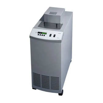
Page 27: Parts And Controls
Parts and Controls Control Panel The following controls and indicators are present on the controller front panel (see Figure 2 below): (1) the digital LED display, (2) the control buttons, (3) the on/off power switch, (4) the heater mode light, and (5) the cooling on/off switch. -
Page 28: Bath Tank And Lid
The user may drill or cut holes in the cover to accommo- date the instruments to be calibrated or immersed in the bath. Spare cov- ers are available from GE Kaye Instruments. An optional access cover which provides locations for two reference thermometers and three wells for units under test is available. -
Page 29: Figure 3 Back Panel
Figure 3 Back Panel The system fuses are 20 amp SB, 250V for 115 VAC operation and 10 amp ST, 250 V for 230 VAC operation. The power cord is rated at 115 VAC, 20 amps. (230 VAC, 10 amps op- tional.) A drain plug is provided for ease of removing the fluid media from the bath. -
Page 30: General Operation
General Operation Bath Fluid Many fluids work with the CTR –80 bath. Choosing a fluid requires consider- ation of many important characteristics of the fluid. Among these are tempera- ture range, viscosity, specific heat, thermal conductivity, thermal expansion, electrical resistivity, fluid lifetime, safety, and cost. If the viscosity becomes too great, the stirrer may not function. -
Page 31: Thermal Conductivity
8 General Operation 8.1.4 Thermal Conductivity Thermal conductivity measures how easily heat flows through the fluid. Ther- mal conductivity of the fluid affects the control stability, temperature unifor- mity, and probe temperature settling time. Fluids with higher conductivity distribute heat more quickly and evenly improving bath performance. 8.1.5 Thermal Expansion Thermal expansion describes how the volume of the fluid changes with temper-... -
Page 32: Cost
flash point is the temperature at which there is sufficient vapor given off so that when there is sufficient oxygen present and a ignition source is applied the va- por will ignite. This does not necessarily mean that fire will be sustained at the flash point. -
Page 33: Mineral Oil
8 General Operation 8.1.10.3 Mineral Oil Mineral oil or paraffin oil is often used at moderate temperatures above the range of water. Mineral oil is relatively inexpensive. At lower temperatures mineral oil is quite viscous and control may be poor. At higher temperatures vapor emission becomes significant. -
Page 34: Limitations And Disclaimer
Specifications may change and sources sometimes offer differing information. GE Kaye Instruments cannot be liable for any personal injury or damage to equipment, product or facilities re- sulting from the use of these fluids. -
Page 35: Stirring
8 General Operation policies regarding flash points, toxicity, and such issues must be considered. You are responsible for reading the (material safety data sheets) and acting accordingly. Stirring Stirring of the bath fluid is very important for stable temperature control. The fluid must be mixed well for good temperature uniformity and fast controller response. -
Page 36: Operation
The compressor manufacturer does not warranty their compressors when used with non-standard refrigerants. Warranty of these compressors must be handled through GE Kaye Instruments only. There is no other way for you to receive parts or service on your compressor. You must receive your parts or service from GE Kaye Instruments. - Page 37 8 General Operation The bath is operable within the temperature range given in the specifications. For protection against solid-state relay failure or other circuit failure, a thermo- couple cutout automatically turns off the heater anytime the bath temperature exceeds the maximum temperature. The controller allows the operator to set the bath temperature with high resolu- tion, adjust the proportional band, monitor the heater output power, and pro- gram the controller configuration and calibration parameters.
-
Page 38: Controller Operation
Controller Operation This section discusses in detail how to operate the bath temperature controller using the front control panel. Using the front panel key-switches and LED dis- play the user may monitor the bath temperature, set the temperature set-point in degrees C or F, monitor the heater output power, adjust the controller propor- tional band, and program the calibration parameters, operating parameters, and serial interface configuration. -
Page 39: Figure 4 Controller Operation Flowchart
9 Controller Operation Display Temperature Select Setpoint Adjust Setpoint Units °C/°F Scan On/Off Scan Rate Menu Legend: Press “SET” to step through the menu and to store the parameter value. Press “EXIT” briefly to skip a parameter without storing the parameter value. Hold “EXIT”... -
Page 40: Set-Point Value
To set the temperature one must first select the set-point memory. This function is accessed from the temperature display function by pressing “SET”. The number of the set-point memory currently being used is shown at the left on the display followed by the current set-point value. 10.00C Access set-point memory 1. -
Page 41: Scan
9 Controller Operation Un= C Press “UP” or “DOWN” to change the units. Un= F Scan The scan rate can be set and enabled so that when the set-point is changed the bath heats or cools at a specified rate (degrees per minute) until it reaches the new set-point. -
Page 42: Secondary Menu
Press “SET” to accept the new scan rate and continue. Accept scan rate Secondary Menu Functions which are used less often are accessed within the secondary menu. The secondary menu is accessed by pressing “SET” and “EXIT” simulta- neously and then releasing. The first function in the secondary menu is the heater power display. - Page 43 9 Controller Operation down. In this way the temperature is maintained at a fairly constant temperature. The temperature stability of the bath and response time depend on the width of the proportional band. If the band is too wide the temperature will deviate ex- cessively from the set-point due to varying external conditions.
-
Page 44: Cutout
Cutout As a protection against software or hardware fault or user error, the bath is equipped with an adjustable cutout device that shuts off power to the heater if the temperature exceeds a set value. This protects the instrument, probes, and fluid from excessive temperatures. -
Page 45: Controller Configuration
9 Controller Operation Controller Configuration The controller has a number of configuration and operating options and calibra- tion parameters which are programmable via the front panel. These are ac- cessed from the secondary menu after the proportional band function by pressing “SET”. -
Page 46: Cooling
Press “SET” to enable adjustment of LL. L=-90 Adjust the LL parameter using “UP” or “DOWN”. L=-20 Press “SET” to accept the new temperature limit. 9.9.3 Cooling This menu function allows the operator to disable cooling and corresponds to the remote cooling control function (see Table 3). Switching the cooling off temporarily allows the bath to heat up more quickly from a low temperature. -
Page 47: Baud Rate
9 Controller Operation 9.10.1 Baud Rate The baud rate is the first parameter in the menu. The baud rate setting deter- mines the serial communications transmission rate. The baud rate parameter is indicated by, bAUd 2400 b The baud rate of the serial communications may be programmed to 300, 600, 1200, 2400, 4800, or 9600 baud. -
Page 48: Linefeed
dUPL d=FULL The mode may be changed using “UP” or “DOWN” and pressing “SET”. d=HALF 9.10.4 Linefeed The final parameter in the serial interface menu is the linefeed mode. This pa- rameter enables (on) or disables (off) transmission of a linefeed character (LF, ASCII 10) after transmission of any carriage-return. -
Page 49: Hard Cutout
9 Controller Operation The calibration parameters R resistance-temperature relationship of the platinum control sensor. These pa- rameters may be adjusted by an experienced user to improve the accuracy of the bath. 9.11.1 Hard Cutout This parameter is the temperature above which the unit shuts down automati- cally. -
Page 50: Digital Communication Interface
10 Digital Communication Interface Digital Communication Interface The CTR –80 Bath calibrator is capable of communicating with and being con- trolled by other equipment through the digital serial interface. With a digital interface the instrument may be connected to a computer or other equipment. -
Page 51: Wiring
10 Digital Communication Interface 10.1.1 Wiring The serial communications ca- ble attaches to the calibrator through the DB-9 connector at the back of the instrument. Fig- ure 5 shows the pin-out of this connector and suggested cable wiring. To eliminate noise the serial cable should be shielded with low resistance between the connector (DB-9) and the... -
Page 52: Sample Period
10.1.2.2 Sample Period The sample period is the next parameter in the menu and prompted with “SPEr”. The sample period is the time period in seconds between temperature measurements transmitted from the serial interface. If the sample rate is set to 5, the instrument transmits the current measurement over the serial interface ap- proximately every five seconds. -
Page 53: Table 3 Controller Communications Commands
10 Digital Communication Interface Table 3 Controller Communications Commands Command Command Description Format Display Temperature Read current set-point s[etpoint] Set current set-point to n s[etpoint]=n Read temperature t[emperature] Read temperature units u[nits] Set temperature units to Celsius u[nits]=c Set temperature units to u[nits]=f Fahrenheit Read scan mode... -
Page 54: Table 3 Controller Communications Commands Continued
Controller Communications Commands continued Command Command Description Format Set serial linefeed mode to on lf[eed]=on Set serial linefeed mode to off lf[eed]=of[f] Read R0 calibration parameter r[0] Set R0 calibration parameter to n r[0]=n Read ALPHA calibration parameter al[pha] Set ALPHA calibration parameter al[pha]=n to n Read DELTA calibration parameter de[lta]... -
Page 55: Calibration Procedure
Calibration Procedure 11.1 Calibration Procedure Calibration of this instrument should be performed at regularly scheduled inter- vals by qualified authorized personnel in accordance with your company’s pol- icy. Following is the recommended procedure for calibrating this instrument. 11.1.1 Calibration Equipment Calibration requires a standard thermometer that is adequately accurate and fits properly into one of the reference holes in the block. - Page 56 11 Calibration Procedure Set the set-point to 50°C and allow adequate time for the bath to reach this temperature and stabilize. Adjust the DELTA calibration parameter (see Section 9.11.4) to make the bath temperature as measured with the standard thermometer match the set-point. The approximate ratio between a change in DELTA and a change in temperature at 50°C is about 4.0 to 1.
-
Page 57: Maintenance
If there are any questions, call GE Kaye Instruments Customer Service for more informa- tion. Before using any cleaning or decontamination method except those rec- ommended by Kaye, users should check with GE Kaye Instruments Cus-... - Page 58 12 Maintenance tomer Service to be sure that the proposed method will not damage the equipment. The condensing coil should be cleaned regularly. Inspect the coil through the vented rear panel. If any dust or dirt accumulation is visible, remove the rear panel to clean out the dust or dirt.
-
Page 59: Troubleshooting
“err 7" - This error means there is a HtrCTL error Cycle the power off and on again. If the unit repeats the error code, con- tact GE Kaye Instruments Customer Support for a return authorization and for assistance. The bath does not turn on If a fault condition exists upon application of power, the bath will not en- ergize. -
Page 60: Trouble Shooting
13 Trouble Shooting If a High/Low voltage condition exists for longer than 5 seconds, the compressor will be de-energized. The controller display will flash “Lo LinE“ o and off while the condition exists. Re-energization is automatic upon correction of the fault condition and af- ter a delay cycle of about 2 minutes. -
Page 61: Wiring Diagram
13.3 Wiring Diagram Wht/Yel/Blk Blue 115V 230V Brown Green/Yel Brown Blue Figure 6 Wiring Diagram SHLD Wht/Org/Blk Vio 18 Wht/Vio/Blk Wht/Vio/Blk 13 Trouble Shooting Wht/Org Wht/Vio...
Need help?
Do you have a question about the CTR 80 and is the answer not in the manual?
Questions and answers