Table of Contents
Advertisement
Advertisement
Table of Contents

Summary of Contents for Hanshin Machinery GRH 3 series
- Page 1 User’s Manual of Compressor...
- Page 2 DANGER Be sure to check airend rotating direction when operating the compressor for the first time after installation. If it rotates in the opposite direction, the airend can be damaged. Be sure to check the rotating direction ! The user s manual is prepared, based on GRH3-100A. Read this manual carefully before installing and operating the compressor and use it properly.
- Page 3 GRH3 star-delta User’s Manual Preface Thank you for purchasing Hanshin Compressor. Hanshin Screw Compressor is the product developed by our long history, abundant experience and accumulated technology. The screw compressor has been verified for the performance by examined design and appropriate reliability test and is conveniently programmed to be optimally operated when the control-related data are automatically calculated and changed if a user simply changes the operation pressure by Micom s control almost close to AI.
-
Page 4: Table Of Contents
GRH3 star-delta User’s Manual Contents About how to use the manual 1. About Safety General Cautions About Marks and Symbols Check Caution/Warning Label Safety Rules Installation Place and Cautions for Installation Cautions for Electric Wiring Cautions for Operation Cautions for Stoppage Cautions for Maintenance 2. -
Page 5: About How To Use The Manual
GRH3 star-delta User’s Manual About how to use the manual The screw compressor is intended to be used domestically (the Republic of Korea). The manual describes the routine operation, repair and maintenance of the manual as well as the installation, general management and periodic maintenance of it. Before installing the compressor, carefully read this manual, fully understand it and follow the description. -
Page 6: About Safety
About how to use the manual 1. About Safety 1. About Safety For the safety purpose, read the cautions and warnings specified in the manual carefully and fully understand them for proper use. The chapter especially highlights the safety items. 1-1 General Cautions The installation, operation, preservation, repair and other works of the product should be executed by a competent engineer. -
Page 7: Check Caution/Warning Label
GRH3 star-delta User’s Manual 1-3 Check Caution/Warning Label 1. GRH3-20A, 25A, 30A, 35A, 50A Caution Caution Discharge pressure ejection Electric shock When checking/replacing parts, the compressor The power should be off before checking the electric should stop with the pressure set to 0 box because of the danger of electric shock. - Page 8 1. About Safety Warning Be careful of being rolled by rotation Do not touch yourself or other articles on any rotating parts such as main/fan motor. The power should be off before repair, maintenance and other works Caution Caution Cautious of Inhalation Beware of a scald Poorly-ventilated indoor operation may cause death Oil cooler, air end and tank may be very hot during...
- Page 9 GRH3 star-delta User’s Manual 2. GRH3-75A, 100A Caution Caution Discharge pressure ejection Electric shock When checking/replacing parts, the compressor The power should be off before checking the electric should stop with the pressure set to 0 box because of the danger of electric shock. A special attention should be paid around a safe After turning it off, a sign, “Power-off for check”...
- Page 10 1. About Safety Warning Be careful of being rolled by rotation Do not touch yourself or other articles on any rotating parts such as main/fan motor. The power should be off before repair, maintenance and other works Caution Caution Cautious of Inhalation Beware of a scald Poorly-ventilated indoor operation may cause death Oil cooler, air end and tank may be very hot during...
-
Page 11: Safety Rules
GRH3 star-delta User’s Manual 1-4 Safety Rules Common rules Before operating, maintaining or repairing the compressor, fully understand the manual. Make sure to wear proper safety devices and uniform when repairing or maintaining the compressor. Especially, when assembling or disassembling a heavy article, you should put on helmet and safety boots. - Page 12 1. About Safety Transportaion Using a forklift When transporting the product, it needs covering with a cloth to avoid scratch or transformation. A forklift used to transport it should be a suitable type to avoid overturn and other accidents. Using a crane When transporting the compressor using a crane, check the load and slowly moveit by using a rope or a crane.
-
Page 13: Installation Place And Cautions For Installation
GRH3 star-delta User’s Manual 1-5 Installation Place and Cautions for Installation Place The compressor is designed to use indoors. Please avoid installing it outside. Installing in a place directly exposed to raindrops or underground with hot ambient temperature may cause electric shock, drain or rust. Caution Installing the compressor in a place with vibration may cause bad contact, destruction of air end and... -
Page 14: Cautions For Electric Wiring
1. About Safety 1-6 Cautions for Electric Wiring Wiring Wiring should be executed in accordance with the indoor wiring rules of the common industrial technology standard, electric facility standards. Wiring should be executed only by a competent electrician. When wiring on the terminals of the compressor, it should be wired to avoid any bending part while a hole into which wires are penetrated should be protected for the sheath from vibration by using rubber and other materials. -
Page 15: Cautions For Operation
GRH3 star-delta User’s Manual 1-7 Cautions for Operation If a trouble occurs, immediately stop the operation to avoid any physical injuries or damages on the compressor. In an emergency, promptly press Caution Emergency Stop button to stop it. The compressor’s discharge pressure is very high. Never inject it toward a person. - Page 16 1. About Safety Do not touch any hot parts of the compressor during or just after operation. Also, during maintenance, do not touch yourself on them. It may cause a serious Caution scald. Make sure to turn off the power before handling the main motor or fan motor.
-
Page 17: Cautions For Stop
GRH3 star-delta User’s Manual 1-8 Cautions for Stoppage Stoppage for a long while Parallel Operation Operation Stoppage Valve closed Turn off the main power when the compressor Once the compressor stops, close the ball and is not used for period of long time. valve of the discharge pipes to avoid any Operate it once a week for, at least, 30 minutes backward flowing of water and other materials. -
Page 18: Names Of Parts
1. About Safety 2. Names of Parts 2. Names of Parts 2-1 GRH3-20A, 25A, 30A, 35A, 50A Fully understand the names and functions of parts relating to the routine operation and manage the compressor. 1. Appearance Front side upper cover vent duct connector Micom right-side door(R) - Page 19 GRH3 star-delta User’s Manual 2. Inside discharge pipe cooling fan Oil/After cooler control panel internal pressure discharge pressure gauge connection power cable motor pully connection oil inlet pully belt oil gauge inhalation valve oil discharge valve aie end pully holding pressure valve vent duct safety valve...
-
Page 20: Grh3-75A, 100A
2. Names of Parts 2-2 GRH3-75A, 100A Fully understand the names and functions of parts relating to the routine operation and manage the compressor. 1. Appearance Front side upper cover vent duct connector right-side door front-right door compressed air front-left door discharge outlet oil gauge window right-side door... - Page 21 GRH3 star-delta User’s Manual 2. Inside Oil/After cooler thermostat valve control panel holding pressure power cable valve connection internal pressure control parts gauge internal safety valve puressure switch inhanlation filter separator tank oil inlet oil filter oil discharge valve oil gauge inhanlation valve cooling fan air end...
-
Page 22: Electric Wiring
2. Names of Parts 3. Electic Wiring 3. Electic Wiring 3-1 Wiring The lead-in cabling to the compressor should be executed by an competent engineer. Any poor wiring may cause electic shock or other electric fault. Do not alter control parts or electric circuits attached to the electric box. The compressor may be damaged due to malfunction of protection. - Page 23 GRH3 star-delta User’s Manual 4. Installation of circuit breaker for wiring If any impurities or dust is found inside when visually inspecting it, turn it off and clean it up Attach a circuit breaker for wiring on the primary with compressed air. power supply of the compressor.
-
Page 24: Power Facilities
3. Electic Wiring 4. Circuit breaker capacity 3-2 Power Facilities The main power supply essentially needs a circuit 1. Cable thickness breaker to avoid electric shock and protect the motor. Since the compressor may not work properly depending When selecting a breaker, refer to the following table. on the power facility capacity and the thickness/length of the power cable and it may stop due to voltage Main motor... -
Page 25: Installation And Piping
GRH3 star-delta User’s Manual 4. Installation and Piping 4-1 Identification of the product specifications When accepting and unpacking the compressor, please check the specifications such as pressure, voltage and frequency by using the plate attached on the left side. Check whether there is any damage/scratch or transformation on covers during the transportation. 4-2 Cautions for Transportation Using a forklift Using a crane... -
Page 26: Cautions For Installation
4. Installation and Piping 4-3 Cautions for Installation The production can be used for a standard life as long as the installation place is well selected. Do not leave any dangerous(flammable) materials around the compressor. It may cause a fire resulting from the heat generated during the operation. Do not attempt any work potentially inducing a fire. - Page 27 GRH3 star-delta User’s Manual Install the compressor in a leveled place with little noise reflection Install it horizontally Do not use any hard block as Cautious against noise on the ground a strut reflection from walls Install the compressor indoors only. If the compressor is installed outside, it may cause a trouble due to moisture and dust.
- Page 28 4. Installation and Piping 3. Ventilation of compressor’s room If the temperature of the compressor’s room is higher than the allowable temperature range, install a forced ventilation facility to ventilate promptly. Operating the compressor at 40 and higher for a long time may cause a fatal fault.
- Page 29 GRH3 star-delta User’s Manual 4. Installation of Ventilator When installing a ventilator, refer to the following figure. If the compressor is installed in an airtight place or a place with lower ceiling, install the air inlet and vent opening as presented in the left figure and attach ventilation fan on the opening.
-
Page 30: Cautions For Piping
4. Installation and Piping 4-4 Cautions of Piping 5. In case of a vertically upright pipe, give a distance about 600mm and more from the cover surface considering the repair works 1. General piping When connecting a pipe to the main air pipe, connect a flange or union to the compressor’s discharge pipe to facilitate the repair, maintenance and disassembly of the compressor... - Page 31 GRH3 star-delta User’s Manual 7. Cautions for parallel piping Completely, close the stop valve of the discharge valve at the compressor that is manually stopped Operating during the operation. Stop valve opened If opening the stop valve of the suspended compressor, the backward pressure is allowed to Stopping After Cooler at the compressor, generating a...
- Page 32 4. Installation and Piping 9. Receiver tank The drain pipe on the bottom of the receiver tank should discharge the condensed water 4 times and more per week. For the capacity of the receiver tank by the compressor capacity, refer to the following table. Drain valve Compressor GRH3-20A...
-
Page 33: Micom Controller
GRH3 star-delta User’s Manual 5. Operations 5-1 Micom Controller 1. Micom Controller consists of LCD display, LED lamps, push button switches and data setting button. Graphic Display The operation is graphically displayed. The brightness is automatically adjusted, depending on the ambient temperature. The bright and clear display facilitates repairs in a dark place. - Page 34 5. Operations 2. Rear view of the Micom Controller Wiring diagram of pressure and temperature sensor Cable Color Signal Name White White Front Cable Color Signal Name Black White SIGNAL Shield Cable Fuse 250V /5A Micom PCB Detail CN2 CN5 CN6 CN3 CN4 (Lubricant oil temperature) Temp.
-
Page 35: Operation Control
GRH3 star-delta User’s Manual 5-2 Operation Control 3. Remote Operation A compressor can be remotely controlled. To 1. Turn on control the operation or stop, wire the Start and Stop buttons in TR2 of the electrical box as If it is turned on with the MCB on inside the presented in the figure below. - Page 36 5. Operations 5-3 Initial Operation & Routine Operation Before operation 1. Initial Operation Check whether the compressor is horizontally installed. Check the internal status of oil level and compressor visually. Connect the pipe at the compressor°Øs discharge side and open the discharge side valve.
- Page 37 GRH3 star-delta User’s Manual During Operation Check whether the oil level is between the normal ranges. If insufficient, stop the compressor, check whether the internal pressure is ‘0’ bar and replenish the oil. Check whether it operates under the specified pressure.
- Page 38 5. Operations When changing the operation conditions such 2. Routine Operation as operation pressure, refer to page 49. Opening the front cover, check whether the The initial values of operation pressure are as compressor has any impurities or oil leakage. follows.
- Page 39 GRH3 star-delta User’s Manual 5-4 Schedule Operation 1. Check and enter the schedule operation time. For the directions, refer to page 49. Displaying the Displaying pressure start presure detected 2. If selecting Schedule mode by pressing Schedule operation mode button once, the following screen is displayed.
- Page 40 5. Operations 5-5 Remote Operation It is basically structured so that the remote operation, stop control and operation status are outputted to the contact. Just attach the Start and Stop buttons as presented in the below figure. 1. Remote Operation 4.
-
Page 41: Remote Monitoring System[Micom]
GRH3 star-delta User’s Manual 5-6 Remote Monitoring System [Micom] When it is necessary to remotely monitor compressor operation, stop and operation status, using [Remote Monitoring Control System] may facilitate the management of the compressor. It is structured as follows. <Specifications> Dimensions: 320(W) x 270(H) x 120(D) Power Supply: AC220V Single Phase 50VA Connection Control Cable: UTP Lan Cable 1 cable... - Page 42 5. Operations 5-7 Remote monitoring System [Computer] When remotely monitoring compressor operation, stop control and operation status, using [Remote Monitoring Control System] may facilitate the control of the compressor, it is structured as follows. Components: computer, COM card[computer], COM cable No.
-
Page 43: Micom Display Configuration & Operations
GRH3 star-delta User’s Manual 5-8 Micom Display Configuration & Operations 1. Display Configuration Micom display consists of 4 screens; main operation screen, auxiliary operation screen, operation status screen and data setup screen. 2. Screen Operation flow Auxiliary Operation Screen It displays operation frequency, no load frequency, filter and operation time. -
Page 44: Operation Data Setup And Check
5. Operations 5-9 Operation Data Setup and Check 1. Operation Display [Main Screen] Display discharge pressure / discharge temp. /total operation time To go to the auxiliary operation screen, press [ ] button. PRES : 9.9 - operation pressure display TEMP : 999 - discharge temperature display OPER : compressor’s total operation hours [Auxiliary Screen]... - Page 45 GRH3 star-delta User’s Manual [Abnormal Temp. sensor, Trip display] When the discharge temperature detection sensor is in trouble “pxx” troubleshooting page is displayed Refer to page 53 and control circuit Checkpoint : temperature sensor, temperature sensor wiring [Abnormal pressure sensor, Trip display] When the discharge pressure control sensor is in trouble “pxx”...
- Page 46 5. Operations [Line pressure rise auto start stand-by display] Auto start stand-by display when the compressor’s internal pressure [P2] is higher than the setting after [START ]button It automatically starts when P2 pressure falls under 6.0 bar. [No load operation display] No-load operation when the pressure rises higher than the no-load start pressure due to reduced air volume.
- Page 47 GRH3 star-delta User’s Manual [Schedule operation display] When the compressor operates by schedules or is waiting for the start. The left figure is displayed when pressing schedule operation button. If pressing START button after selecting schedule operation mode, it operates and stops according to the pre-defined time.
- Page 48 5. Operations 2. Operation Data Setup Operation data setup items AR01: [ ] AR02: Operation diff. pressure AR03: Operation pressure AR04: [ ] Press [ ]button on Main screen AR05: Auto start diff. pressure the main screen. AR06: [ ] T01: Y-D switchover time T02: auto stop time T03: [ ]...
- Page 49 GRH3 star-delta User’s Manual If placing the cursor on [AR02] and pressing [ENT] button, the left figure is displayed. Operation diff. pressure change Move the cursor on 1 1.0, press [ENT] button, change the data by using [ ] buttons and press [ENT], completing the data change if pressing [ESC].
- Page 50 5. Operations Y-D switchover Second time setting Place the cursor on [T01] and press [ENT] button. Then, the left screen appears. Place the cursor on 1 05, press [ENT] button, change the data by using [ ] buttons and press [ENT] button, completing the data change.
-
Page 51: Protective Devices And Lcd Message List
GRH3 star-delta User’s Manual 6. Troubleshooting 6-1 Protective Devices and LCD Message List 1. Protective Devices The following protective devices are contained to protect the compressor against dangerous situation and the measures should be taken by referring the functions. 63A(pressure switch for internal pressure detection) 49M1 (Fan motor overload relay) Operation Operation... -
Page 52: Trouble Causes And Measures
6. Troubleshooting 6-2 Trouble Causes and Measures 1. Fan motor overload, trip Causes: fan motor overload or wrong connection of fan motor power cable Checkpoint: check the current and electric wiring If overload is found as a result of measuring the current, check it as follows. - Page 53 GRH3 star-delta User’s Manual 5. Abnormal temp. sensor , trip Causes: temperature sensor fault Checkpoint: Check sensor cable connection, sensor cable disconnection and sensor. Take a measure by referring to the following figure. How to reset: After taking a measure, press [STOP] button of Micom. Micom PCB Check whether the connector is correctly inserted to...
- Page 54 6. Troubleshooting 8. Troubleshooting flowchart Trouble Checklist Potential trouble causes Main motor overload trip The compressor does not Fan motor overload trip Is the red lamp on [TRIP] start even though pressing Pressure sensor fault of Micom on? [START] button of Micom. Temp.
- Page 55 GRH3 star-delta User’s Manual Trouble Checklist Potential trouble causes The belt is cut off Is the belt or coupling The main motor rotates but The coupling is correctly connected and is the the pressure does not rise. separated air end properly rotating? Is the inhalation valve Inhalation valve fault completely open?
- Page 56 6. Troubleshooting Trouble Checklist Potential trouble causes The safety valve suddenly Does the safety valve operate Safety valve fault operates during operation within the rated pressure? Re-set the pressure Is the operation pressure set according to the rated below the rated pressure? pressure.
-
Page 57: Regular Maintenance
GRH3 star-delta User’s Manual 7. Maintenance 7-1 Regular Maintenanc Before maintenance and check, read [About Safety] carefully. Every time you maintain the compressor, make sure to turn off the power. Or, it may cause unexpected accidents such as electric shock. When coupling or disassembling parts, discharge the internal pressure to the air. -
Page 58: Maintenance Method
7. Maintenance 7-2 Maintenance Methods 1. Replacement and cleaning of inhalation filter / 3000hr The inhalation filter diff. pressure during operation is 4.98kpa [508mmH2O]. The inhalation filter should be maintained according to the standard Inhalation filter cover maintenance criteria. Open the front left of the sound proof cover. Open the inhalation filter cover and detach the filter. - Page 59 GRH3 star-delta User’s Manual Open the front left of the sound proof cover. Loosen the upper bolt of separator tank by using spanner and other tools. High pressure hose Loosen the high pressure hose. Fixed bolt Replace the separator and gasket. Visually check whether the compressor has any oil leakage during operation after replacement.
-
Page 60: Compressor Configuration Layout
8. Control System 8. Control System 8-1 Compressor Configuration Layout 60 / Hanshin... -
Page 61: Control Circuit
GRH3 star-delta User’s Manual 8-2 Control circuit 1. Analogue Controller (ACP-2007) GRH3-20A~35A... - Page 62 8. Control System 2. Micom Controller GRH3-50A~100A 62 / Hanshin...
- Page 63 GRH3 star-delta User’s Manual GRH3-25A, 30A, 35A, 50A Star-delta...
- Page 64 8. Control System GRH3-75A, 100A Star-delta 64 / Hanshin...
-
Page 65: Operation Flow Chart
GRH3 star-delta User’s Manual 8-3 Operation flow chart 1. Control flow chart Start and operation flow chart Load operation Check any fault Display fault Check P2 pressure Release the fault Fault occurs message 7.0 bar Start approved No load operation Press START button No load operation... - Page 66 8. Control System 2. Pressure Control Graph(Operation setting pressure: 7.0bar) Discharge presusre(bar) P1:Internal pressure P2:Pressure in use Time Section: compressor load operation section If P2 pressure is lower than the no-load start pressure after the compressor starts, it starts load operation. Sections: compressor no-load operation section If P2 pressure is higher than the no-load start pressure, it operates under no load up to 6.0bar;...
-
Page 67: Arrangement Diagram And Spec. Of Control Parts
GRH3 star-delta User’s Manual 8-4 Arrangement Diagram and Spec. of Control Parts 1. Inside View of Electrical Box GRH3-20A, 25A, 30A, 35A, 50A Analog controller 63AX 49M2 Transformer MCCB 49M1 Micom controller Transformer MCCB 49M2 Power supply 42 52 49M1 6 42 52 Controller Emergency Stop button... - Page 68 8. Control System 2. Inside View of Electrical Box(Micom Controller) GRH3-75A,100A GRH3-75A, 100A Transformer MCCB Power supply 49M2 49M1 GRH3-75W, 100W Transformer Power supply MCCB1 MCCB2 49M2 68 / Hanshin...
- Page 69 GRH3 star-delta User’s Manual 2. Spec. of Major control parts Spec. of AC220V / 60Hz control parts Input voltage: AC220V Item GRH-3 Mark Name Manufacturer GRH3-20A GRH3-50A GRH3-75A GRH3-100A 25A, 30A, 35A Cable-wiring MCCB LS IS BS32a-6A circuit-breaker Terminal block Geonheung KH6060-3 KH60100-3...
- Page 70 9. Specifications 9. Specifications GRH3 GRH3 GRH3 GRH3 GRH3 GRH3 GRH3 Model 100A TYPE Single Stage Oil Injection Screw Air Compressor 10.3 13.6 7.0 bar CAPACITY FAD* 12.0 8.5 bar /min) 10.7 9.9 bar OIL CAPACITY( ) Gear driven DRIVING METHOD Belt driven Direct STARTING...
- Page 71 GRH3 star-delta User’s Manual 10. Maintenance Checklist Check or cleaning Replacement Check period Notes Check Parts to check 1 mth 2 mths 6 mths 1 yr 2 yrs 4 yrs point Daily 500h 1000h 3000h 6000h 12000h 24000h Check Check indication Temp.
- Page 72 10. Maintenance Checklist 11. Operation Log 11. Operation Log 72 / Hanshin...
- Page 73 GRH3 star-delta User’s Manual 12. Quality Warranty 1. Warranty Warranty period of major parts Notes Warranty period(first occurrence) Parts Period Based on the date of use Based on the date of delivery Air end 24 months 30 months 6 months 12 months Instrumentation and control parts Other parts...
- Page 74 12. Quality Warranty 13. Outside Drawing by Models 13. Outside Drawing by Models 1. GRH3-20A, 25A, 30A, 35A 74 / Hanshin...
- Page 75 GRH3 star-delta User’s Manual 2. GRH3-50A...
- Page 76 13. Outside Drawing by Models 3. GRH3-75A, 100A 76 / Hanshin...
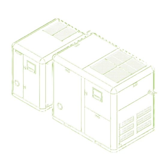
- Page 77 GRH3 star-delta User’s Manual 4. GRH3-75W, 100W Appearance...
- Page 78 13. Outside Drawing by Models Inside control panel discharge pressure connection power cable holding pressure connection valve internal pressure control parts gauge internal safety valve puressure switch separator tank inhanlation filter oil inlet oil filter water in oil discharge valve water out oil gauge after cooler...
Need help?
Do you have a question about the GRH 3 series and is the answer not in the manual?
Questions and answers