
Summary of Contents for SunPlus HL410
- Page 1 H.264 DVR User Manual 4CH DVR ━ ━ This document contains preliminary information and subject to change without notice.
- Page 2 WARNING TO REDUCE THE RISK OF FIRE OR ELECTRIC SHOCK, DO NOT EXPOSE THIS APPLIANCE TO RAIN OR MOISTURE. NOTE: This equipment has been tested and found to comply with the limits for a class digital device, pursuant to part 15 of the FCC Rules.
-
Page 3: Table Of Contents
Conents CHAPTER 1 PACKING DETAIL AND INSTALLATION …………………. 1-1 Packing ………………………………………………………………………………... CHAPTER 2 PANEL LOCATION ………………………………………..2-1 Front Panel Controls ………………………………………………………………… 2-2 Rear Panel Connectors ……………………………………………………………… CHAPTER 3 SPECIFICATIONS ……………………………………………. CHAPTER 4 LIVE, PLAYBACK AND PTZ OPERATIONS …....4-1 Live Mode …………………………………………………………………………….. 4-1.1 Remote Controller …………………………………………………………….. - Page 4 5-8.2.1 Change Date & Time ………………………………………………… 5-8.2.2 Time Zone Setup …………………………………………………….. 5-8.2.3 Internet Time Setup ………………………………………………….. 5-8.3 Buzzer & Relay Setup ………………………………………………………… 5-8.4 SPOT Setup ……………………………………………………………... 5-9 Utility Setup …………………………………………………………………………… 5-10 Diagnostic …………………………………………………………………………… CHAPTER 6 BACKUP & SEARCH ………………………………………... 6-1 Backup Setup ………………………………………………………………………… 6-2 Search Setup …………………………………………………………………....
- Page 5 CHAPTER 9 CMS INSTALLATION AND USAGE GUIDE ………………. 9-1 CMS Installation ……………………………………………………………………… 9-2 CMS Login and Environment ……………………………………………………….. 9-3 DVRs, Groups & Events …………………………………………………………….. 9-3.1 View DVR╱Group List ……………………………………………………….. 9-3.2 View Event Logs ……..……………………………………………………….. 9-4 Local PC Information and Control ………………………………………………….. 9-5 Main Display …………………………………………………………………………..
-
Page 6: Chapter 1 Packing Detail And Installation
CHAPTER 1 PACKING DETAIL AND INSTALLATION 1-1 PACKING 1. DVR 2. User Manual 3. IR Remote Control 4. Batteries x 2 5. CD 6. Power Adapter 7. Power Cord 8. HDD Screws x 4... -
Page 7: Chapter 2 Panel Location
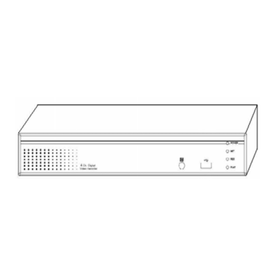
CHAPTER 2 PANEL LOCATION 2-1 FRONT PANEL CONTROLS ① ③ ② Control Keys Description POWER:Power is on. NET:Remote user logged in. ① LED DISPLAY REC:Recording. PLAY:Playing back. ② USB 2.0 PORT Port for USB external devices. ③ IR SENSOR Input sensor for the remote control. 2-2 REAR PANEL CONNECTORS ①... -
Page 8: Chapter 3 Specifications
CHAPTER 3 SPECIFICAITONS 1. VIDEO Input Level 1.0 Vp-p±10% Composite, 75Ω Balanced NTSC 120fps (4CH) Display Speed 100fps (4CH) NTSC 720 x 480 Display Resolution 720 x 576 Monitor Output 2Vp-p Composite, 75Ω Balanced 2. RECORDING Compression Method H.264 Recording Speed Refer to table 3-1 NTSC 720 x 480, 720 x 240, 352 x 240... - Page 9 7. ENVIRONMENTAL ℃ ℃ Operation Temperature ~ + 40 Humidity Less than 90% 8. PHYSICAL Dimension 95 (W) x 440 (D) x 280(H) mm Weight 2.6kg 9. BACKUP USB Stick Video Data, Audio BACKUP Network Video Data, Audio 10. SEARCHING & PLAYBACK Event∕Time Searching Method 11.
-
Page 10: Chapter 4 Live, Playback And Ptz Operations
CHAPTER 4 LIVE, PLAYBACK AND PTZ OPERATIONS The IR remote control and mouse operate differently under each mode; this chapter describes the functions of them under three different modes: LIVE, PLAYBACK and PTZ. 4-1 LIVE MODE You can monitor all the channels, listen to audio signal and have some related operations under LIVE mode. -
Page 11: 4-1.1 Remote Controller
4-1.1 REMOTE CONTROLLER Table 4-1.1 Remote control functions under the LIVE mode Button Name Description . REC Start/Stop recording. Audio ◀◀ ▶▶ Fast forward;Pause;Stop;Fast rewind ▌▌ ■ ⁄ . BK-UP Display backup menu. ⁄ . STATUS Display status. Press this button to slow-down playback . - Page 12 Table 4-1.2 Graphical icons that appeared after right-clicked on the mouse under LIVE mode. Icon Description Icon Description Setup Pause Main Menu PIP, picture in picture Search Setup ZOOM, double the screen size Backup Auto-Sequence PTZ Control LOCK, activate the key lock. Record On∕Off Full Screen Playback...
-
Page 13: Playback Mode
4-2 PLAYBACK MODE Switch to PLAYBACK mode by pressing “PLAY” under the LIVE mode, the graphical icon will show up on the upper center of the screen and the operation panel (see below picture) will show up at right lower corner of the screen. You can drag the panel by mouse to place it on any location of your screen. -
Page 14: Ptz Mode
4-3 PTZ MODE Switch to the PTZ mode by pressing “PTZ” button under the LIVE mode. The PTZ icon will appear on upper left of the screen but it can be re-located on any place of your screen by dragging the mouse. Table 4-3.1 Remote Control functions under the PTZ mode Button Description... - Page 15 Table 4-3.2 Mouse operation under the PTZ mode Icon Description Leave PTZ Mode, back to the LIVE mode. Pre-set number N. (1~64). Go to pre-set number N. Set current PTZ location at pre-set number N. 「TOUR」, press to activate pre-set tour. 「PIP」, Set current PTZ location as the start of the line-scan.
-
Page 16: Chapter 5 Main Menu Setup
CHAPTER 5 MAIN MENU SETUP To enter the main menu and set up DVR, log-in account and user password are required. The default password of the administrator is “123456”. Please check the “ACCOUNT SETUP” for related setup of other log-in users. Table 5-0.1 Definition of the virtual keyboard. -
Page 17: Record Setup
Table 5-0.2 The operation of remote control under the setting menu Item Description Switch to different options under one item. Switch to different items. MENU Save setup and back to LIVE mode. BK-UP∕ESC Back to Upper level of menu without saving. ENTER Enter the menu, or display virtual keyboard. -
Page 18: 5-1.1 Quality & Frame Rate Setup
5-1.1 QUALITY & FRAME RATE SETUP Item Description RESOLUTION Choose record resolution from:CIF∕HD1 (2CIF)∕D1. RECORD TYPE You can setup quality and FPS separately for record type. Check∕uncheck the box will enable∕disable recording of that channel. QUALITY Choose from Lowest∕Low∕Normal∕High∕Highest. Choose recording frame rate. 5-2 EVENT SETUP Item Description... -
Page 19: 5-2.1 Motion Setup
5-2.1 MOTION SETUP Item Description Check the box to Enable∕Disable Motion Detection for all MOTION DETECTION channels. Check the box to Enable∕Disable popup screen function for all MOTION POPUP channels. When motion is detected in LIVE mode, the detected channel image will pop up in full screen display. You can setup independently for each channel. -
Page 20: 5-2.1.1 Motion Area Setup
5-2.1.1 MOTION AREA SETUP The motion area setup allows users to select multiple areas where camera should watch for motion detection. The default area is entire screen. Click and drag the cursor without lifting to mark your selected motion detection area. Item Description LOCK∕ZOOM... -
Page 21: Schedule Setup
Item Description Check the box to Enable∕Disable sensor detection for all SENSOR DETECTION channels. Check the box to Enable∕Disable popup screen function for all SENSOR POPUP channels. When Sensor is detected in LIVE mode, the detected channel image will pop up in full screen display. Click or press ▼... -
Page 22: 5-3.1 Schedule Record Setup
5-3.1 SCHEDULE RECORD SETUP Click on the time on the left side. The setup menu will be displayed. You can have detail setup by Dates, Time and Event. 5-3.2 HOLIDAY SETUP Since holidays are different by different country and region, you can setup the holiday of your location accordingly. -
Page 23: Camera Setup
5-4 CAMERA SETUP Item Description You can setup independently for each channel. Check the box to Enable∕Disable mask function for LIVE mode MASK Drag the white bar or press to adjust Brightness of your camera BRIGHTNESS from value 1 to 255. The default value is 128. Drag the white bar or press to adjust Contrast of your camera CONTRAST... -
Page 24: Account Setup
5-5 ACCOUNT SETUP The Account Setup menu is used to provide role-based permission independently setting for each user (maximum of 4 users) to access DVR over network. The default admin account is 「admin」and password is “123456”. Item Description Function Auto Logout Key Lock Setting ○... -
Page 25: 5-5.1 Permission Setup
5-5.1 PERMISSION SETUP The Account Setup is set to provide individual user (maximum of 4 users) role-based permissions, including access to Setup menu, Network operation, PTZ function, Playback, Utility, Backup and Mask on specific channels while playing back. 5-6 NETWORKING SETUP Item Description Setup mode for network connection:DHCP、LAN、ADSL. -
Page 26: 5-6.1 Networking Setup
5-6.1 NETWORKING SETUP The DVR supports DHCP, LAN and ADSL accesses for network connection. If the settings are subsequently changed, pressing “PLAY” button to drive new settings for re-connection is required. 5-6.1.1 DHCP If the DHCP option is used for DVR network connection, an IP address is assigned by the DHCP server automatically. -
Page 27: 5-6.1.3 Adsl
5-6.1.3 ADSL Select ADSL for network connection, the following information is required. Item Description USER NAME Enter user name provided by ISP PASSWORD Enter password provided by ISP 5-6.2 HTTP SETUP Item Description ENABLE HTTP Check to enable HTTP server. Users can remotely access into the SERVER DVR over the network if the HTTP function is activated. -
Page 28: 5-6.3 Ddns Setup
5-6.3 DDNS SETUP Item Description Check∕Uncheck to enable∕disable DDNS function. ENABLE DDNS Enter the registered SMTP Server: DDNS SERVER DYNDNS.ORG、NO-IP.ORG、CUSTOM.COM SMTP SERVER Enter the registered SMTP Server. USER NAME Enter user name. PASSWORD Enter password. 5-6.4 MAIL SETUP E-mail can be used as a form of notification when an event occurs (VLOSS, MOTION, and SENSOR). -
Page 29: Ptz & Rs485 Setup
Item Description ENABLE E-MAIL Check the box to enable∕disable E-mal Notification function. NOTIFICATION SMTP SERVER Enter to set up SMTP Serve name. USER NAME Enter to set up User Name. PASSWORD Enter to set up Password. SENDER E-MAIL Enter to set up e-mail address of sender. E-MAIL ADDRESS Enter to set up e-mail addresses for up to 10 receivers individually. -
Page 30: System Setup
5-8 SYSTEM SETUP Item Description DVR NAME The name of DVR will be shown when users login from remote access. The location of DVR will be shown when users login from remote DVR LOCATION access. Click or press ▼ to select OSD language from English, Chinese, Greek, LANGUAGE Italian, Japanese, Portuguese, Spanish, German, French, Russian or Polish. -
Page 31: 5-8.1 Display Setup
5-8.1 DISPLAY SETUP Item Description Turn On∕Off OSD display Turn On∕Off DVR illustration and record status display DVR STATUS DATE/TIME Turn On∕Off date and time display Turn On∕Off message display MESSAGE Turn On∕Off channel name display CHANNEL NAME Set up the color of border in LIVE1, PLAYBACK mode.(black、dark BORDER SET grey、light grey、white)... -
Page 32: 5-8.2.1 Change Date & Time
Item Description 12HOURS∕24HOURS HOUR FORMAT MM-DD-YY∕DD-MM-YY∕YY-MM-DD DATE FORMAT DATE/TIME POSITION Choose the position of Time and Date display CHANGE DATE & TIME Setup time and date of DVR TIME ZONE SETUP Setup GMT and Daylight Saving Time. INTERNET TIME SETUP Setup automatic synchronization with internet server 5-8.2.1 CHANGE DATE &... -
Page 33: 5-8.3 Buzzer & Relay Setup
Item Description Check to enable DVR automatic synchronization function. AUTOMATIC Effective by this option selected, DVR will automatically SYNCHRONIZATION synchronize the time upon rebooting or by every 24 hours after booting. Effectively, Date and Time show on DVR will immediately UPDATE NOW correspond with those in internet server. -
Page 34: 5-8.4 Spot Setup
5-8.4 SPOT SETUP The DVR has two modes of video output; one is main video output, the other is spot video output. SPOT setup is for controlling the order of channels the system cycles through in SPOT mode. User can monitor every channel in the SPOT mode. Item Description Channels display in spot for three different modes:... -
Page 35: Utility Setup
5-9 UTILITY SETUP Item Description Select to enter initialize hard disk menu. Please stop recording before entering this menu. Enter the menu, system will show all the data (model, volume) of HDD that HDD INITIALIZATION installed in DVR. Check the HDD you’d like to initialize then press “START”. -
Page 36: Diagnostic
5-10 DIAGNOSTIC Item Description VERSION The current firmware version of DVR The connected IP address of DVR. If disconnected from IP ADDRESS network, the screen will display “NETWORK DISCONNECT”. MAC ADDRESS MAC Address of DVR HDD VOLUME The capacity of HDD HDD USED RATE Percentage of space used on HDD. -
Page 37: Chapter 6 Backup & Search
CHAPTER 6 BACKUP & SEARCH 6-1 BACKUP SETUP User can backup any segment of recorded data in a specified time frame. To do so, either a Remote Network or storage device, like USB, must be connected to the DVR. The format of backup file is IRF file that can be played by “DVRemoteDesktop.exe”... -
Page 38: Search Setup
6-2 SEARCH SETUP Item Description EVENT SEARCH Press to enter event search menu TIME SEARCH Press to enter time search menu... -
Page 39: 6-2.1 Event Search
6-2.1 EVENT SEARCH The DVR automatically records events with type, time and channel information included. If there is recording data for an event, the recording signal will be shown on the left side of time information. Rest your cursor under the line and press “ENTER”, or left click your mouse to playback the recording data. -
Page 40: 6-2.1.1 Criteria Setup For Event Search
6-2.1.1 CRITERIA SETUP FOR EVENT SEARCH The amount of events can be numerous. Therefore, you can facilitate event sorting by setting up “CRITERIA”. Setup “START TIME” and “END TIME” for event search, then the search result will be limited to this specific period of time. Only checked events and channels will be sorted in event search as well. -
Page 41: 6-2.2 Time Search
6-2.2 TIME SEARCH TIME SEARCH can search for the specific time of recording data to playback. To specify a date, use ◀ or ▶ to move the cursor up and down, use ▲▼ or roll the mouse to change dates. Press “ENTER”... -
Page 42: Chapter 7 Network Surveillance
CHAPTER 7 NETWORK SURVEILLANCE 7-1 IE SETUP Step One:Enter the IP address of DVR in IE browser. Here you may choose to setup IE remote or download the AP software. Step Two:Click OK when window prompts to install an ActiveX for IE remote. After Please enter the user name and password. - Page 43 Step Three:Please enter information of login DVR: IP, Port, Username and Password, or choose “PLAY RECORDED FILE” to open backup files in your PC. Step Four:You’ve logged into the DVR...
-
Page 44: Ap Software Installation And Setup
7-2 AP SOFTWARE INSTALLATION AND SETUP AP software:「DVR Remote Desktop」can allow you to remotely access and control the DVR from PC. Step One:Enter the IP address of DVR in IE browser. Note:This IP is only for reference. Please setup your local IP. Step Two:Below windows will be shown up. - Page 45 Step Four:Run or Save our AP software. Step Five:If you choose to run the software, Start window will be shown up. Please enter information of login DVR: IP, Port, Username and Password, or choose “PLAY RECORDED FILE” to open backup files in your PC. Step Six:You’ve logged into the DVR...
-
Page 46: Ap Software Operation
7-3 AP SOFTWARE OPERATION Open the file “DVRemoteDesktop.exe”; enter the information of DVR “IP ADDRESS”, “PORT” “USERNAME” and “PASSWORD” and click “OK”. You should be able to login DVR successfully and start to use the software. The default username and password is 「admin/123456」 The operation of AP software remains the same as local DVR;... -
Page 47: Chapter 8 Mobile Application Installation And Usage
CHAPTER 8 MOBILE APPLICATION INSTALLATION AND USAGE You can remotely monitor all channels of DVR through your mobile device. The required mobile application is from DVR manufacturer and it supports mobile OS for both Windows mobile 5.0 above and Symbian. Please confirm network function of DVR has been activated before mobile connection:... -
Page 48: 8-1.2.2 Logging Onto The Dvr
8-1.2.2 LOGGING ONTO THE DVR Use the Login command to log onto a DVR and monitor live images. If multiple DVRs have been added to the mobile application, they will be listed by name, you can select one to log onto. A confirmation message might show up for network charge before connection. -
Page 49: 8-1.2.4 Delete The Login Information Of Dvr
8-1.2.4 DELETE THE LOGIN INFORMATION OF DVR “DELETE” command can be used to remove the DVR information if it is no longer useful. Select the DVR on the name list then choose “DELETE” 8-1.3 LIVE MONITORING OPERATION This paragraph describes some operation under the LIVE monitoring mode in your mobile device. -
Page 50: 8-1.3.2 Image Quality Setup
8-1.3.2 IMAGE QUALITY SETUP Select “QUALITY” under the “MENU” There will be 5 levels for your to choose: Low、Normal、Middle、High and Highest. 8-1.3.3 CHANNEL DISPLAY You can choose single or quad channel display for live monitoring. Select “SINGLE” under the “MENU”, there will be all channels of your DVR in list for you to choose. -
Page 51: 8-1.3.5 Rotate The Image
8-1.3.5 ROTATE THE IMAGE The Live image can be displayed in normal or rotate to 90 degrees. Select “ROTATE” under the “MENU” for this operation. 8-1.3.6 ALARM This application not only allows you to remotely monitor through mobile device but receive the alarm that has been triggered by events such as Motion Detected, Sensor Triggered and Vloss. -
Page 52: 8-2.1 Mobile Application Installation
8-2.1 MOBILE APPLICATION INSTALLATION Please follow the steps cited below to perform the mobile device surveillance function on your mobile device (mobile phone, PDA...etc). Step 1:The mobile application called “Jrviewer” and “H264Pocket.CAB” need to be installed in your mobile device. The application can be downloaded directly from the manufacturer’s website to your mobile or;... -
Page 53: 8-2.3 Operation Under The Live Monitoring
Item Function Description Enter DVR’s name, IP address, Port, Account user, Password Add login DVR then press “OK” Choose the DVR that you’d like to log on, then press “OK”. PS. The Live cannot be displayed in your mobile when the recoding is off. LOGIN Logon DVR PS. -
Page 54: 8-2.3.1 Operation Under The Live Monitoring For Jrviewer
8-2.3.1 OPERATION UNDER THE LIVE MONITORING FOR JRVIEWER Item Function Description CHANNEL 1~4 Display for CH 1~4 Choose from CH1~4 to display Original:image size as original Stretch:stretch the size as full screen SCREEN Size of image Fit:resize the image to fit the screen Change the quality of image. -
Page 55: 8-2.3.2 Operation Under The Live Monitoring For H264 Pocket
8-2.3.2 OPERATION UNDER THE LIVE MONITORING FOR H.264 POCKET Item Function Description Choose from CH1~4 to display. CHANEEL 1~4 Display for CH 1~4 CH1~4 can receive audio signal. Graphical icons indicated below will be shown on the status bar if there is event such as motion detected, sensor triggered and video loss to be detected on any channel. -
Page 56: Chapter 9 Cms Installation And Usage Guide
CHAPTER 9 CMS INSTALLATION AND USAGE GUIDE 9-1 CMS INSTALLATION System Requirement: Intel Pentium 4 processor or equivalent. Microsoft Windows Vista、Windows XP、Windows 2003 Server. 512MB memory above. (500M requested for group DVR connection and 180M for single DVR) 20MB HD space. Recording and image capturing require extra space for storage. Installation:... - Page 57 5.”CONFIRM INSTALLATION” window shows. Select ‘’EXT” then the installation starts. 6.Select “CLOSE” To finish installation when the “INSTALLATION COMPLETE” window shows.
-
Page 58: Cms Login And Environment
9-2 CMS LOGIN AND ENVIRONMENT To enter CMS, the administrator’s user name and password are entered. The defaults are ‘‘admin’’ and ‘‘123456’’. After successful login, the following image shows on your screen: ③ ① ② ④ ⑤ ① DVRS, GROUPS & Information about DVRs, groups and events. -
Page 59: 9-3.1 View Dvr Group List
/ 9-3.1 VIEW DVR GROUP LIST Single left click on ‘‘DVR’’ or ‘‘GROUP’’ will expand/collapse the entire DVRs and groups list. On the DVR list, double left click on a connected DVR will show its image in the main display. See “9-6.2 DVR ADMINISTRATION”... -
Page 60: Local Pc Information And Control
9-4 LOCAL PC INFORMATION AND CONTROL Located at the left lower corner of the screen, please see the chart below: Icon Function Description Shows the ratio of available space∕HDD size of the HDD INFO C:\ drive (where CMS is installed). VOLUME PC volume or playback volume control bar. -
Page 61: Main Display
9-5 MAIN DISPLAY The main display area is where the live image of DVR is shown. You can drag to change the location of screen for each channel and turn on∕off audio signal with mouse-click. 9-5.1 AUDIO CONTROL In live mode, you can turn on/off the audio signal of CH1~CH4: 「... -
Page 62: 9-5.2 Emap Display
9-5.2 eMAP DISPLAY In Live mode, pressing will bring the e-MAP drag-down menu. If the channel has been set up to use e-MAP, the menu will show all the e-MAP titles that have been entitled to this channel; otherwise, “NO eMAPS” will be shown. Please check “9-6.4 eMAP ADMINISTRATION” for setup information. -
Page 63: Operation Bar
9-6 OPERATION BAR 10 Operations to be listed as below: Table 9-6.1 Description of 10 operations: Icon Description User Administration. Please see “9-6.1 USER ADMINISTRATION” DVR Administration. Please see “9-6.2 DVR ADMINISTRATION” Group Administration. Please see “9-6.3 GROUP ADMINISTRATION” eMap Administration. Please see “9-6.4 eMAP ADMINISTRATION”. Remote Playback. -
Page 64: 9-6.1 User Administration
9-6.1 USER ADMINISTRATION Before the CMS can be used on a PC, user accounts should be added with proper authority. Each user should also be assigned a password and optionally a description. If a user does not have certain authority assigned, he/she will not be able to operate the corresponding function on the Operation Bar. -
Page 65: 9-6.3 Group Administration
9-6.3 GROUP ADMINISTRATION A ‘‘GROUP’’ means a set of video channels from one or many DVRs, which means, user can organize channels from different DVRs to be set in a group. This function allows you to monitor and manager channels from multiple DVRs easily and flexible. Steps:... -
Page 66: 9-6.4 Emap Administration
9-6.4 eMap ADMINISTRATION If geographical locations are relevant, or if it is desired to use a picture as the background, eMap can be used for the purpose. With eMap, the background picture can be picked by the user and channels from multiple DVRs can be placed and dragged around on the picture. Steps to follow:... -
Page 67: 9-6.6 Hdd Playback
Icon Description Start playing. Pause. Fast forward. Fast rewind. 9-6.6 HDD PLAYBACK You can directly play the recording data in the HDD that’s uninstalled from DVR by CMS. See the picture below, the left part of screen is recording data in list that’s separated by hour and the right part is main display. -
Page 68: 9-6.7 File Playback
9-6.7 FILE PLAYBACK You can play the recorded .IRF files by “FILE PLAY” in CMS. It allows you to change the display mode, forward or rewind the file and drag the time bar. Icon Description Start Playback. Pause. Stop playback. Fast forward. -
Page 70: 9-6.9 Snapshot Data
9-6.9 SNAPSHOT DATA It can display all the snapshots you’ve taken in line in “SNAPSHOT DATA”. You can review, delete or save as other files here. 9-6.10 RECORDING DATA It can play all the recording files you’ve recorded in line in “RECORDING DATA”. You can play or delete them here. -
Page 71: Appendix I Hard Disk Installation
APPENDIX I HARD DISK INSTALLATION I-1 HARD DISK INSTALLATION Step 1) Check the screws in the package for the screw hole. Step 2) Put the HDD on the HDD plate and screw it as indicated. Step 3) Screw the bottom of the DVR as indicated to fix the HDD. - Page 72 Step 4) Connect the power and the SATA cables as indicated.
Need help?
Do you have a question about the HL410 and is the answer not in the manual?
Questions and answers