Table of Contents
Advertisement
Advertisement
Table of Contents

Summary of Contents for DualLite LiteGear
-
Page 1: Installation Instructions
Installation Instructions and User Manual 250 VA Inverter Power System... -
Page 2: Save These Instructions
The installation and use of this product must comply with all national, federal, state, municipal, or local codes that apply. Please read this manual thoroughly before operating the LiteGear Inverter System. For technical assistance, contact Dual-Lite’s Systems Technical Support Center at... -
Page 3: Table Of Contents
Table of Contents Description Page 100. Installation ..................................4-5 ........................4 100.1 General Installation Requirements 100.2 Cabinet Installation................................4 101. AC Connections ................................5-6 101.1 General Precautionary Measures ............................5 101.2 AC Wiring Preparations ................................ 5 101.3 AC Input Voltage Selection ................................6 102. -
Page 4: Installation
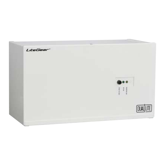
General Installation Requirements CAUTION: LiteGear cabinets are very heavy. Check to assure that the chosen location is capable of safely bearing the load. Cabinet Size: 18.375” W x 10.2” H x 8.25” D (46.6cm W x 25.9cm H x 21cm D) Weight (including batteries): 70 lbs. -
Page 5: Ac Connections
AC connections to the LiteGear inverter system. The LiteGear inverter system is only designed to supply 120 VAC in/120 VAC out or 277 VAC in/277 VAC out. Only authorized persons should disconnect AC to the unit. (See NEC 700-20 and 700- 21.) Use of this equipment for simultaneous operation of 120VAC and 277VAC loads will damage the unit and void the warranty. -
Page 6: 101.3 Ac Input Voltage Selection
101.3 AC Input Voltage Selection The battery charger transformer has two input leads: black = 120VAC orange = 277VAC Select proper AC input lead for the application. Refer to Fig. 101-2. For 120VAC input: • Black – Connect to FT2 •... -
Page 7: Installing The Batteries And Dc Wiring
Remove rings and metal wristwatches or other metal objects and jewelry. Don’t carry metal objects in pockets where the objects can fall onto the batteries or into the LiteGear inverter system. -
Page 8: 103.3 Battery Installation Procedure
103.3 Battery Installation Procedure Place the batteries into the cabinet as shown in Figure 103-1. Connect one end of the provided gray wire to the Negative Terminal (-) of battery 1 to the Positive Terminal (+) of battery 2. Connect the red wire from the electronic module to the Positive Terminal (+) of battery 1, and connect the blue wire to the Negative Terminal (-) of battery 2. -
Page 9: 103.4 Electronics Cabinet Voltage Check
• Ensure the LiteGear Inverter cabinet is securely fastened to a wall or other structure. • Ensure that the input circuit breaker in the building service panel serving as the AC supply to the LiteGear system is in the OFF position. -
Page 10: Status Indicators
200. Status Indicators 200.1 Indicators Provided The LiteGear system is equipped with two LED indicators: LED Display System Mode Reason None • No AC power • Low Voltage Battery Disconnect circuit activated following extended power outage • Batteries disconnected Amber Inverter-ON •... -
Page 11: 201.2 Trouble Shooting Service Alert Code Faults
Automatic Tests: • Unit tested once every month (28 days) for one minute duration • Unit tested every six months alternating between 30 and 60 minute duration. • Pressing the test button will end an automatic test routine Service Alert Code One blink on/pause Battery not connected Two blinks on/pause... -
Page 12: Maintenance
CAUTION: To avoid possible equipment damage or personal injury, assume that there is AC voltage present inside the LiteGear inverter cabinet when AC input power or DC battery voltage is present. The inverter is capable of providing output voltage from the batteries even when there is no AC input line voltage. When AC input voltage is present, the unit can provide output voltage even when the batteries are disconnected. -
Page 13: 300.4 Manual Routine Inverter Tests
The LiteGear system incorporates a test switch to facilitate monthly testing. Simply depress the button and hold to test the inverter at anytime. Once released, the LiteGear will revert back to standby operation. For annual 90-minute discharge or other prolonged tests, de-energize the AC breaker at the service panel. -
Page 14: 300.8 Battery Replacement Procedure
CAUTION: • Lengthy storage of batteries will cause irreversible damage to the cells. • Failure to connect LiteGear inverter system batteries to an energized charging circuit within 90 days from the date of shipment will void the battery warranty. 302.1... - Page 15 Notes:...
- Page 16 Dual-Lite • www.dual-lite.com A Hubbell Lighting, Inc. brand with representatives’ offices in principal cities throughout North America. Copyright Hubbell Lighitng, Inc., All Rights Reserved • Specifications subject to change without notice. • Printed in U.S.A. © 0603471 B 10/10...


Need help?
Do you have a question about the LiteGear and is the answer not in the manual?
Questions and answers