Table of Contents
Advertisement
Quick Links
Model 620 – ±50 A, ±5 V
Model 622 – ±125 A, ±30 V
Methods and apparatus disclosed and described herein have been developed solely on company funds of Lake Shore Cryotronics, Inc.
No government or other contractual support or relationship whatsoever has existed which in any way affects or mitigates proprietary
rights of Lake Shore Cryotronics, Inc. in these developments. Methods and apparatus disclosed herein may be subject to U.S. Patents
existing or applied for. Lake Shore Cryotronics, Inc. reserves the right to add, improve, modify, or withdraw functions, design
modifications, or products at any time without notice. Lake Shore shall not be liable for errors contained herein or for incidental or
consequential damages in connection with furnishing, performance, or use of this material.
Rev. 1.2
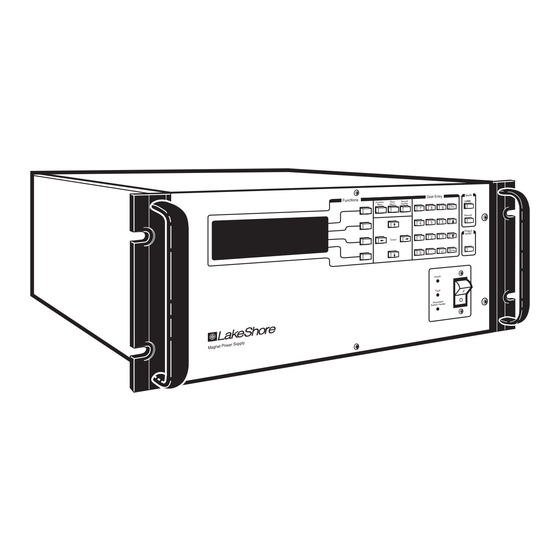
User's Manual
Model 620/622/623/647
Model 620/622/623/647
Model 620/622/623/647
Model 620/622/623/647
Magnet Power Supply
ly
w er Su pp
M ag ne t Po
Model 623 – ±155 A, ±30 V
Model 647 – ±72 A, ±32 V
Lake Shore Cryotronics, Inc.
575 McCorkle Blvd.
Westerville, Ohio 43082-8888 USA
E-Mail Addresses:
sales@lakeshore.com
service@lakeshore.com
Visit Our Website:
www.lakeshore.com
Fax: (614) 891-1392
Telephone: (614) 891-2243
P/N 119-001
Mode
Data Entry
Funct ions
Loca l
Local
Next
Normal
Function
Display
Menu
Menu
9
9
Esc
Esc
8
8
7
7
Remo te
6
5
4
Output
Inhibit
3
2
1
Cursor
.
Ente r
+/-
0
Pow er
Fau lt
Per sist ent
ter
Sw itch Hea
9 April 1999
Advertisement
Table of Contents


Need help?
Do you have a question about the 620 and is the answer not in the manual?
Questions and answers