Table of Contents
Advertisement
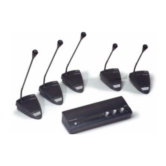
CCS 800 Ultro
zh-t
zh-s
th
ja
Installation and Operating Manual
en
Discussion System
Manuel d'installation et d'utilisation
fr
Système de Discussion
Installations- und Bedienungshandbuch
Diskussionssystem
de
Manual de instalación y funcionamiento
es
Sistema de Conferencias
Installatie- en gebruikshandleiding
nl
Discussiesysteem
Installazione e Manuale operativo
it
Sistema audio congressuale
Advertisement
Table of Contents

Subscribe to Our Youtube Channel
Related Manuals for Bosch CCS 800 Ultro


Summary of Contents for Bosch CCS 800 Ultro
- Page 1 CCS 800 Ultro Installation and Operating Manual Discussion System Manuel d’installation et d’utilisation Système de Discussion Installations- und Bedienungshandbuch Diskussionssystem zh-t Manual de instalación y funcionamiento zh-s Sistema de Conferencias Installatie- en gebruikshandleiding Discussiesysteem Installazione e Manuale operativo Sistema audio congressuale...
- Page 2 Page Prior to installing or operating this product always read ..................... the Safety Instructions which are available as a separate document. Avant d 'installer ou d'utiliser ce produit, lisez toujours .................... les Instructions de sécurité disponibles dans un docu- ment distinct. Lesen Sie vor Installation oder Inbetriebnahme dieses ..................
-
Page 3: About This Manual
About this manual Introduction This "Instructions For Use" manual provides all the The CCS 800 Ultro Discussion System is a discussion information required to install and operate the CCS 800 system for use in meeting and conference venues with a Ultro Discussion System. - Page 4 CCS 800 Ultro | Installation and Operating Manual en | 6 Control and power supply 4 Speaker volume control of all connected delegate and chairman units. unit (CPSU) 5 Volume control of the speaker or headphone of the CPSU. 6 Headphone connection with 3.5 mm stereo jackplug socket.
-
Page 5: Delegate And Chairman Unit
CCS 800 Ultro | Installation and Operating Manual en | 7 14 Mains input connection. Use the included mains 9 Chairman Priority button. When pressed emits cord to connect the CPSU to the mains socket. chime tone, overrules/mutes all active microphones... -
Page 6: Connecting Up To 150 Units
CCS 800 Ultro | Installation and Operating Manual en | 8 5.2 Connecting up to 150 units CCS 800 Ultro can be used with up to 150 units by adding maximum 2 additional control units acting as power supply units only. The system is controlled by the master LBB 3310. - Page 7 CCS 800 Ultro | Installation and Operating Manual en | 9 5.5 Connecting a wireless Connect the cabling of the tape recorder (2) to the microphone recorder input and output of the CPSU (1). Use the gain control (3) to adjust the sensitivity of the recorder input of the CPSU.
-
Page 8: Connecting A Telephone Coupler
5. 1 0 Mains connection isolation between the telephone network (PBX) and the CCS 800 Ultro system. The telephone coupler shall also meet all relevant requirements for this type of Trunk in/out... - Page 9 CCS 800 Ultro | Installation and Operating Manual en | 11 Operation 6. 1 Testing the connection of the delegate and chairman units CCS 800 ULTRO Figure 6. 1 Put the mode selector in the test position, all light-ring indicators and LEDs of the delegate and chairman units must lit if properly connected.
-
Page 10: Using The Priority Button
CCS 800 Ultro | Installation and Operating Manual en | 12 6.3 Using the microphone button of the chairman unit 1...4 1...4 Figure 6.3 Pressing the microphone button on a chairman unit 6.5 Priority mode settings in always activates the chairman microphone, independent chairman unit of the selected microphone mode. -
Page 11: Open Mode
CCS 800 Ultro | Installation and Operating Manual en | 13 6.6 Open mode Select the max. number ( 1, 2, 3 or 4) of delegate microphones which can be active at the same time. Note Chairmen can always switch on and off their microphones and are not included in the max. -
Page 12: Override Mode
CCS 800 Ultro | Installation and Operating Manual en | 14 6.8 Override mode CCS 800 ULTRO Figure 6.8 Each time a delegate presses the microphone button on a delegate unit, it will override the currently active delegate unit. So only one delegate microphone is active at the same time. - Page 13 CCS 800 Ultro | Installation and Operating Manual en | 15 6. 1 0 Volume control of the delegate and chairman units CCS 800 ULTRO Figure 6. 1 0 Turn the volume control (1) to set the volume of the loudspeakers of the delegate and chairman units (2).
-
Page 14: Monitoring Volume Control
CCS 800 Ultro | Installation and Operating Manual en | 16 6. 1 2 Monitoring volume control CCS 800 ULTRO Figure 6. 1 2 6. 1 3 Using a headphone Use the built-in loudspeaker or a headphone to monitor the discussion. Adjust the volume using the monitoring volume control. -
Page 15: Troubleshooting
CCS 800 Ultro | Installation and Operating Manual en | 17 Troubleshooting Part of system not working Possible cause • Temporary no microphone reaction, and no sound or Interrupted trunk-line cabling. distorted sound from unit loudspeakers Solution • Possible cause •... -
Page 16: Technical Data
CCS 800 Ultro | Installation and Operating Manual en | 18 Technical data Monitor loudspeaker Output level at 0.5 m: 72 dB SPL/ 82 dB SPL (nominal/maximum) 8. 1 System Electrical and Electro- Frequency response: 320 Hz ... 10 kHz Acoustical Characteristics (-10 dB, ref. -
Page 17: General Data
CCS 800 Ultro | Installation and Operating Manual en | 19 8.3 General Data 8.1.2 Combined Units Delegate microphones with transmission links to 8.3.1 System Environmental Conditions delegate headphones and auxiliary outputs. Temperature range General Storage and transport: -20 to +70°C (-4 to +158°F) Frequency response: 125 Hz - 12.5 kHz tolerances... - Page 18 CCS 800 Ultro | Installation and Operating Manual en | 20 8.3.2Equipment Range Control and power supply unit: LBB 3310/00 LBB 3310/10 (with Digital Acoustic Feedback Suppression) 19" rack mounting set: LBB 3311/00 Bracket for flush mounting: can be made locally according to...
-
Page 19: Pin Configuration
CCS 800 Ultro | Installation and Operating Manual en | 21 Appendix 9. 1 Pin Configuration CCS 800 ULTRO Trunk in/out Microphone Recorder Line Telephone Insertion Digital Acoustic Gain Gain Feedback Suppression 90-260 V~ Figure 9. 1 9.1.1 Trunk Connections (A) 9.1.2 External Microphone (XLR) (B) -
Page 20: Mounting Instructions
CCS 800 Ultro | Installation and Operating Manual en | 22 9.2 Mounting Instructions 9.1.5 Headphone Jack-plug (3.5mm) (E) 1 Tip - Signal + 2 Ring - Signal - The CPSU can be attached in three different ways: 3 Sleeve - Electrical earth/screen •... -
Page 21: Bracket For Flush Mounting
CCS 800 Ultro | Installation and Operating Manual en | 23 9.3 Bracket for Flush Mounting The drawing below gives the necessary information how to make a bracket for flush mounting the CPSU into a table. 90˚ ø8.6(4x) 4.6 (2x) 50.3... - Page 23 For more information please visit www.boschsecuritysystems.com © 2003 Bosch Security Systems B.V. Data subject to change without notice June 03 | 3922 988 54284...
Need help?
Do you have a question about the CCS 800 Ultro and is the answer not in the manual?
Questions and answers
So master cpsu is different from slave cpsu like in it's appearance
The provided context does not mention any differences in appearance between the master CPSU and the slave CPSU for the Bosch CCS 800 Ultro. It only states that there can be one master CPSU and up to two slave CPSUs in a system.
This answer is automatically generated
How is master cpsu and slave connected like diagram (setup)
The Bosch CCS 800 Ultro system connects the master CPSU and slave units using trunk connections. The trunk in/out connections are labeled in the pin configuration as follows:
- Trunk Connections (A):
- Pin 1: Audio contribution line
- Pin 2: GND (0V, phantom supply)
- Pin 3: Audio distribution line
- Pin 4: Control line 1
- Pin 5: Control line 2
- Pin 6: V+ supply
- Pin 7: V- supply
These connections ensure communication and power distribution between the master CPSU and any connected slave units.
This answer is automatically generated
Clarify more on how to connect all 3 cpsu and 150 units, setups and how to set master and slave cpu
To connect three CPSUs and 150 units in a Bosch CCS 800 Ultro setup:
1. Connect the Units: The CCS 800 Ultro system can support up to 150 units by adding up to 2 additional CPSUs (Control and Power Supply Units). Each CPSU provides power and connectivity for the units.
2. Master and Slave Configuration:
- The system is controlled by the master CPSU (LBB 3310).
- The two additional CPSUs act as power supply units only (slaves).
- The master CPSU manages the system, while the slave CPSUs provide additional power for the units.
3. Cabling:
- Connect delegate and chairman units in a loop-through manner using the provided 7-pole circular connectors.
- Use extension cables if necessary to connect distant units.
- The required cables can be obtained from a local dealer.
By following these steps, the system can support and manage up to 150 units efficiently.
This answer is automatically generated
Clarify on How to connect all Three cpsu and all 150 units
To connect all three CPSU units and 150 units for the Bosch CCS 800 Ultro system:
1. Max Units Per CPSU: The system supports up to 150 units by adding a maximum of two additional CPSU units, acting as power supply units only.
2. Master Control Unit: The system is controlled by the master unit (LBB 3310).
3. Unit Distribution: A maximum of 6 groups of 25 units can be connected.
4. Connection Setup:
- Connect the delegate and chairman units to the trunk connectors of the CPSU.
- Use an extension cable if necessary.
- Additional CPSU units provide extra power but are not control units.
5. Cabling: Necessary cables for these connections must be obtained from the local dealer.
This setup ensures proper power distribution and functionality of the system.
This answer is automatically generated
Is it like line output of the slave cpsu connected to the line input of the Master cpsu