Advertisement
Quick Links
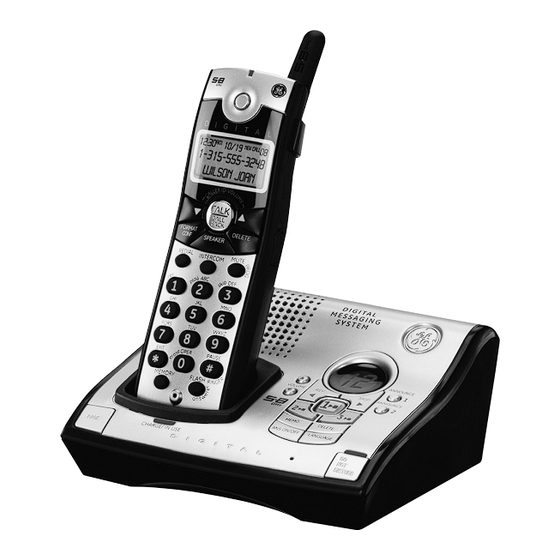
Model 28031 Series
25840
2 Rights of the Telephone Company
Should your equipment cause trouble on y our line which may harm the telephone
network, the telephone company shall, where practicable, notify you that temporary
5.8 GHz Cordless
discontinuance of service may be required. Where prior notice is not practicable and the
circumstances warrant such action, the telephone company may temporarily discontinue
Handset Speakerphone
service immediately. In case of such temporary discontinuance, the telephone company
must: (1) promptly notify you of such temporary discontinuance; (2) afford you the
opportunity to correct the situation; and (3) inform you of your right to bring a complaint
Answering System
to the Commission pursuant to procedures set forth in Subpart E of Part 68, FCC Rules and
Regulations.
User's Guide
The telephone company may make changes in its communications facilities, equipment,
operations or procedures where such action is required in the operation of its business and
not inconsistent with FCC Rules and Regulations. If these changes are expected to affect
the use or performance of your telephone equipment, the telephone company must give
you adequate notice, in writing, to allow you to maintain uninterrupted service.
Interference Information
This device complies with Part 15 of the FCC Rules. Operation is subject to the following two
conditions: (1) This device may not cause harmful interference; and (2) This device must accept
any interference received, including interference that may cause undesired operation.
This equipment has been tested and found to comply with the limits for a Class B digital device,
pursuant to Part 15 of the FCC Rules. These limits are designed to provide reasonable protection
against harmful interference in a residential installation.
This equipment generates, uses, and can radiate radio frequency energy and, if not installed
and used in accordance with the instructions, may cause harmful interference to radio
communications. However, there is no guarantee that interference will not occur in a particular
installation.
Privacy of Communications may not be ensured when using this product.
If this equipment does cause harmful interference to radio or television reception, which can be
determined by turning the equipment off and on, the user is encouraged to try to correct the
interference by one or more of the following measures:
• Reorient or relocate the receiving antenna (that is, the antenna for radio or television that is
"receiving" the interference).
• Reorient or relocate and increase the separation between the telecommunications
equipment and receiving antenna.
• Connect the telecommunications equipment into an outlet on a circuit different from that to
which the receiving antenna is connected.
Your new GE telephone system is EXPANDABLE
If these measures do not eliminate the interference, please consult your dealer or an
up to a total of 4 handsets (by purchase of optional
experienced radio/television technician for additional suggestions. Also, the Federal
Model 28001 handset with charge cradle)
Communications Commission has prepared a helpful booklet, "How To Identify and Resolve
Radio/TV Interference Problems." This booklet is available from the U.S. Government Printing
Equipment Approval Information
Office, Washington, D.C. 20402. Please specify stock number 004-000-00345-4 when ordering
copies.
Your telephone equipment is approved for connection to the Public Switched Telephone
Notice: The changes or modifications not expressly approved by the party responsible for
Network and is in compliance with parts 15 and 68, FCC Rules and Regulations and the
compliance could void the user's authority to operate the equipment.
Technical Requirements for Telephone Terminal Equipment published by ACTA.
Hearing Aid Compatibility (HAC)
1 Notification to the Local Telephone Company
On the bottom of this equipment is a label indicating, among other information, the US
This telephone system meets FCC standards for Hearing Aid Compatibility.
number and Ringer Equivalence Number (REN) for the equipment. You must, upon request,
Licensing
provide this information to your telephone company.
The REN is useful in determining the number of devices you may connect to your
Licensed under US Patent 6,427,009.
telephone line and still have all of these devices ring when your telephone number is
FCC RF Radiation Exposure Statement
called. In most (but not all) areas, the sum of the RENs of all devices connected to one line
should not exceed 5. To be certain of the number of devices you may connect to your line
as determined by the REN, you should contact your local telephone company.
This equipment complies with FCC RF radiation exposure limits set forth for an uncontrolled
A plug and jack used to connect this equipment to the premises wiring and telephone
environment. This equipment should be installed and operated with a minimum distance of
network must comply with the applicable FCC Part 68 rules and requirements adopted
20 centimeters between the radiator and your body. This transmitter must not be co-located
by the ACTA. A compliant telephone cord and modular plug is provided with this product.
or operated in conjunction with any other antenna or transmitter."
It is designed to be connected to a compatible modular jack that is also compliant. See
For body worn operation, this phone has been tested and meets the FCC RF exposure
installation instructions for details.
guidelines when used with the belt clip supplied with this product. Use of other accessories
Notes
may not ensure compliance with FCC RF exposure guidelines.
• This equipment may not be used on coin service provided by the telephone company.
• Party lines are subject to state tariffs, and therefore, you may not be able to use your
own telephone equipment if you are on a party line. Check with your local telephone
company.
• Notice must be given to the telephone company upon permanent disconnection of your
telephone from your line.
• If your home has specially wired alarm equipment connected to the telephone line,
ensure the installation of this product does not disable your alarm equipment. If you have
questions about what will disable alarm equipment, consult your telephone company or
a qualified installer.
THE LIGHTNING
US Number is located on the cabinet bottom.
FLASH AND ARROW
WARNING: TO
HEAD WITHIN THE
REN Number is located on the cabinet bottom.
PREVENT FIRE OR
TRIANGLE IS A
WARNING SIGN
ELECTRICAL SHOCK
ALERTING YOU OF
HAZARD, DO NOT
"DANGEROUS
EXPOSE THIS
VOLTAGE" INSIDE
THE PRODUCT.
PRODUCT TO RAIN
Thomson Inc.
OR MOISTURE.
SEE MARKING ON BOTTOM / BACK OF PRODUCT
10330 North Meridian Street
Model 28031B
Indianapolis, IN 46290
00007707 (Rev. 2 Dom E)
© 2006 Thomson Inc.
06-33
Trademark(s) ® Registered
Printed in China
Marca(s) Registrada(s)
Introduction
CAUTION: When using telephone equipment, there are basic safety
instructions that should always be followed. Refer to the IMPORTANT
SAFETY INSTRUCTIONS provided with this product and save them for
future reference.
IMPORTANT: Because cordless phones operate on electricity, you should
have at least one phone in your home that isn't cordless, in case the power
in your home goes out.
Before You Begin
Parts Checklist
(for model 28031xx1)
Make sure your package includes the items shown here.
Base
Wall mount
Telephone
bracket
line cord
AC power
Battery
Handset
battery pack
adaptor
compartment cover
Belt clip
For Model 28031xx2 there will be ONE additional handset, charge cradle, belt
clip, battery pack and cover than shown above.
For Model 28031xx3 there will be TWO additional handsets, charge cradles,
belt clips, battery packs and covers than shown above.
For Model 28031xx4 there will be THREE additional handsets, charge cradles, belt clips,
battery packs and covers than shown above.
Telephone Jack Requirements
To use this phone, you need an RJ11C type modular telephone
jack, which might look like the one pictured here, installed in
your home. If you don't have a modular jack, call your local
Modular
telephone
phone company to find out how to get one installed.
line jack
Installation
Digital Security System
Your cordless phone uses a digital security system to protect against false ringing,
unauthorized access, and charges to your phone line.
INSTALLATION NOTE: Some cordless telephones operate at frequencies that
may cause or receive interference with nearby TVs, microwave ovens, and
VCRs. To minimize or prevent such interference, the base of the cordless
telephone should not be placed near or on top of a TV, microwave ovens,
or VCR. If such interference continues, move the cordless telephone farther
away from these appliances.
Certain other communications devices may also use the 5.8 GHz frequency
for communication, and, if not properly set, these devices may interfere
with each other and/or your new telephone. If you are concerned with
interference, please refer to the owner's manual for these devices on how to
properly set channels to avoid interference. Typical devices that may use the
5.8 GHz frequency for communication include wireless audio/video senders,
wireless computer networks, multi-handset cordless telephone systems, and
some long-range cordless telephone systems.
Important Installation Guidelines
• Avoid sources of noise and heat, such as motors, fluorescent lighting, microwave
CAUTION:
ovens, heating appliances and direct sunlight.
RISK OF ELECTRIC SHOCK
DO NOT OPEN
CAUTION: TO REDUCE THE
THE EXCLAMATION
• Avoid areas of excessive dust, moisture and low temperature.
RISK OF ELECTRIC SHOCK, DO
POINT WITHIN THE
NOT REMOVE COVER (OR
TRIANGLE IS A
• Avoid other cordless telephones or personal computers.
BACK). NO USER
WARNING SIGN
SERVICEABLE PARTS INSIDE.
ALERTING YOU OF
IMPORTANT
REFER SERVICING TO
• Never install telephone wiring during a lightning storm.
INSTRUCTIONS
QUALIFIED SERVICE
PERSONNEL.
ACCOMPANYING
• Never install telephone jacks in wet locations unless the jack is specifically
THE PRODUCT.
designed for wet locations.
• Never touch non-insulated telephone wires or terminals, unless the telephone line
has been disconnected at the network interface.
• Use caution when installing or modifying telephone lines.
Handset Layout
Installing the Phone
Installing the Handset Battery
In use
NOTE: You must connect the handset battery before use.
(indicator)
CAUTION: To reduce the risk of fire or personal injury, use only the
SPEAKER
Thomson Inc. approved model 5-2660 Nickel-metal Hydride battery
(Ni-MH), which is compatible with this unit.
1. Locate battery and battery door which are packaged together inside a plastic bag
and are separate from the handset.
display
2. Locate the battery compartment on the back of the handset.
3. Plug the battery pack cord into the jack inside the compartment.
TALK/CALL BACK
(button)
NOTE: To ensure proper battery installation, the connector is keyed and can
be inserted only one way.
CALLER ID-VOLUME
CALLER ID-VOLUME
(button)
(button)
FORMAT/CONF
ABC
DEF
(format/conference
DELETE
GHI
JKL
MNO
button)
(button)
PQRS
TUV
WXYZ
EXIT
OPER
PAUSE
SPEAKER
RI
MUTE/PROG
(button)
(mute/program button)
Handset
REDIAL
(button)
4. Insert the battery pack.
INTERCOM
rev (review
(button)
5. Close the battery compartment by pushing the door up until it snaps into place.
button)
Base Station
skip (button)
* EXIT
1. Choose an area near an electrical outlet and a telephone wall jack (RJ11C), and place
(button)
play (button)
your cordless telephone on a level surface, such as a desktop or tabletop, or you may
mount it on the wall.
# PAUSE/
erase
RINGER (button)
(button)
Wall plate
FLASH/answerer
MEMORY
(button)
(button)
Base Layout
HOUR
MIN
DAY/CHECK
(button)
(button)
(minute button)
SPEAKER
VOL
REVIEW
Message
(volume buttons)
indicator
(button)
SKIP
(button)
2. Plug one end of the telephone line cord into the TEL LINE jack on the bottom of the
base and the other end into a modular jack.
3. Plug the AC power converter into the electrical outlet and the DC connector into the
ANNOUNCE 1
jack on the bottom of the base.
(button)
4. Place the handset in the base cradle. The charge/in use indicator turns on, verifying
ANNOUNCE 2
the battery is charging.
(button)
5. Allow the phone to charge for 16 hours prior to first use. If you don't properly charge
PLAY/STOP 1
the phone, battery performance is compromised.
(button/indicator)
CAUTION: Use only the model 5-2733 power adaptor that came with this
unit. Using other power adaptors may damage the unit.
PLAY/STOP 2
(button/indicator)
Wall Mounting
PLAY/STOP 3
1. Turn the base over.
(button/indicator)
2. Attach the wall mounting pedestal by first inserting the tabs on the open edge of
the pedestal into the slots on the lower portion of the bottom of the base. Then push
down and snap the pedestal into place.
DELETE
(button)
3. Slip the mounting holes (on the back of the base) over the wall plate posts, and slide
the unit down into place. (Wall plate not included.)
DO NOT DISTURB
(button)
NOTE : If desired, gather the extra telephone line and power adaptor cord
PAGE
CHARGE/IN USE
MEMO
Microphone
and store inside the wall mounting bracket.
(button)
(button)
(indicator)
ANS ON/OFF
LANGUAGE
(answerer button)
(button)
Answering System Setup
This section shows you how to set up your answering system to receive incoming calls.
Before you begin the set up process, you must turn on the answering system.
• Press the ANS ON/OFF button to turn the answering system on and off.
The MESSAGES indicator lights when the answering system is on. The indicator blinks
when you have new messages.
NOTE: The answering system displays "- -" when it is off.
Setting the Voice Prompt Language
The default voice prompt language is English.
To change the answering system's voice prompt language,
• Press the LANGUAGE button on front of base to change to the FRENCH voice prompt.
The unit announces "OPTION FRANCAISE " and Fr shows in the message counter.
battery
• Press the LANGUAGE button again to change to the SPANISH voice prompt. The unit
pack
announces "SELECCION ESPANOL" and SP shows in the message counter.
black wire
NOTE: To change to English, press the LANGUAGE button again.
NOTE: In remote access mode, the system follows the selected language. The
voice prompt language cannot be switched remotely.
Voice Time/Day Stamp and Real Time Clock
PRESS DOWN
1. Make sure the answering system is ON.
FIRMLY
red wire
2. Press and hold the DAY/CHECK button to set the day of the week.
3. Press and hold the HOUR button to set the hour (a.m. or p.m.). Example: 12AM, 1AM, or
12PM, 1PM.
4. Press and release the MIN button to advance the clock in one minute intervals. Press
and hold to increase by 5-minute increments.
5. After the time is set, the real time clock will be displayed on the handset within 1
minute.
NOTE: You must set the day manually. You may choose to set the time manually
as well, although the time is automatically transmitted by your local phone
company as part of Caller ID service. If you subscribe to Caller ID service, the
current time is set automatically when you receive your first CID record.
Speaker Volume
Use the VOLUME (5 or 6) buttons to adjust speaker volume on the base to a
comfortable level. L1 is the minimum speaker volume and L8 is the maximum.
Voice Instruction
If you need additional assistance, press the REV button in standby mode and follow the
voice instructions.
Recording the Outgoing Announcement
For best results when recording, you should be about nine inches from the microphone,
and eliminate as much background noise as possible.
You may record 2 outgoing announcements in the answerer or choose the default for
your current outgoing announcement.
1. Make sure the answering system is ON.
2. Press and hold the ANNOUNCE 1 or ANNOUNCE 2 button until the speaker announces
"RECORD ANNOUNCEMENT AFTER TONE".
3. Begin speaking after you hear the beep.
4. Release the button when you finish your announcement.
NOTE: If you choose not to record an outgoing announcement, a default
announcement plays instead. To return to the default announcement after
you have recorded your own outgoing announcement, press the ANNOUNCE
1 or 2 button and release it when you hear the beep. Or, press the DELETE
button while the announcement is reviewing.
Sample Outgoing Announcement
1) Sample Single Mailbox Outgoing Announcement
Hi, this is (use your name here), I can't answer the phone right now, so please leave your
name, number and a brief message after the tone, and I'll get back to you. Thanks.
NOTE: The maximum recording time for the outgoing announcement is 2
minutes.
2) Sample Multi-Mailbox Outgoing Announcement
Hi, this is (use your name here), We can't answer the phone right now, so please press 1
to direct your message to (name 1), press 2 to direct your message to (name 2), press 3 to
direct your message to (name 3). Leave your name, number and a brief message after the
tone, and we'll get back to you soon. Thanks.
Reviewing and Choosing the Announcement
Press and release the ANNOUNCE 1 button to review and select this one as your
outgoing announcement. Or, press and release the ANNOUNCE 2 button to review and
select this one as your outgoing announcement.
Programming the Telephone
Standby Screen
The handset displays the handset number and user name.
USER NAME
HANDSET X
Programming Functions
The system uses a menu structure to give you access to all of the built-in features. You
may program the following items in main menu: Room Monitor and Handset Setup.
Room Monitor
(applicable only with additional handsets)
1. Make sure your phone is OFF (not in talk mode).
2. Press the MUTE/PROG button to go to the main menu.
3. Press CALLER ID-VOLUME ( 6 or 5) button to scroll to ROOM MONITOR.
> ROOM MONITOR
HANDSET SETUP
4. Press MUTE/PROG button to enter ROOM MONITOR menu, ROOM MONITOR
EXTENSION? shows in the display.
5. Use the touch tone pad to enter the handset number to be monitored, either 1 or 2.
NOTE: When this phone system is expanded (up to 4 handsets by purchase
of optional Model 28001 handset with recharge cradle), handsets are named
HANDSET 1, HANDSET 2, HANDSET 3 and HANDSET 4 respectively.
6. The receiving handset will turn on the microphone and the originating handset will
turn on the speakerphone to monitor sound from the receiving handset.
NOTE: For room monitoring mode to work, the originating handset must NOT
be on the cradle.
NOTE: While in room monitoring mode, the handsets will emit an alert tone
approximately every 5 seconds if there is an incoming call. You may press
the SPEAKER button to quit room monitor and answer the call.
NOTE: While in room monitoring mode, the originating handset can be
switched to monitor by handset earpiece by pressing the TALK/CALL BACK
button once. Switch back to speakerphone by pressing the SPEAKER
button once.
NOTE: Press the *EXIT button on the handset to exit room monitor mode.
Handset Setup
1. Make sure your phone is OFF (not in talk mode).
2. Press the MUTE/PROG button to go to the main menu.
3. Press CALLER ID-VOLUME ( 6 or 5) button to scroll to HANDSET SETUP.
4. Press MUTE/PROG button to confirm and you may program the following items:
Language, Handset Name, Ringer Tone, Ringer Volume, VIP Melody, Key Tone,
Message Alert, Rings to Answer, Security Code, Area Code, Registration, Deregistration
and Default Setting.
NOTE: During programming, you may press the *EXIT button at any time to
exit the sub-menu and return to the menu.
Advertisement

Related Manuals for GE 28031EE1


Summary of Contents for GE 28031EE1
- Page 1 1. Choose an area near an electrical outlet and a telephone wall jack (RJ11C), and place minute. your cordless telephone on a level surface, such as a desktop or tabletop, or you may NOTE: You must set the day manually. You may choose to set the time manually mount it on the wall.
- Page 2 Language Storing VIP Melody From the Handset Setup Menu: From the Handset Setup Menu: 1. Press the CALLER ID-VOLUME ( 6 or 5) button to scroll to the SET LANGUAGE sub-menu. 1. Press the CALLER ID-VOLUME ( 6 or 5) button to scroll to VIP MELODY sub-menu. 2.
- Page 3 Provided you subscribe to Call Waiting Caller ID service from your phone company; NOTE: Press the *EXIT button once to keep the previous setting (making no if you receive an incoming call and you are using the GE multi handset system, a beep changes) and return to the menu.
- Page 4 Belt Clip and Optional Headset Display Messages Connecting the Belt Clip The following messages shows the status of the phone, provides Caller ID information, or helps you set up and use your phone. 1. To attach the belt clip, insert the sides of the belt clip into the slots on each side of the handset.
Need help?
Do you have a question about the 28031EE1 and is the answer not in the manual?
Questions and answers