Advertisement
Harmony
Remote Repair
Important! Before you begin working on your Harmony 900, you must discharge any static electricity you
may be carrying around. Ideally, you should wear an anti-static wrist strap as you work. If you do not own
an anti-static device, at least touch a grounded appliance (the metal on the back of a computer tower works
well) before you begin working. The components inside the H900 are sensitive to static electricity so it is
very important to take these precautions!
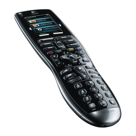
Before you get started, familiarize yourself with the parts pictured below.
Back Cover
harmonyremoterepair.com
Front Cover/ Touchscreen
How to install
your new Harmony 900
Front Cover/Touch Screen
Logic Board
Button Guide
Button Pad (back side)
"Rubberized" Back Plate
Button Pad
(front side)
Page
Advertisement
Table of Contents

Related Manuals for Harmony 900


Summary of Contents for Harmony 900
- Page 1 Front Cover/Touch Screen harmonyremoterepair.com Important! Before you begin working on your Harmony 900, you must discharge any static electricity you may be carrying around. Ideally, you should wear an anti-static wrist strap as you work. If you do not own an anti-static device, at least touch a grounded appliance (the metal on the back of a computer tower works well) before you begin working.
- Page 2 Disassembly Procedure Remove the battery compartment cover. There are four screws in this area that need to be removed. Two are immediately visible on either side of the serial number sticker. Remove them with a small Phillips head screwdriver and set them aside. There are also two hidden screws under the sticker (if there is no sticker, all four screws are visible).
- Page 3 Now, this is probably the trickiest part of the dis- assembly. It is time to separate the two clamshell halves of the 900. A larger bladed pry tool is best for this work. Start with the remote face-up in your hand and take the pry tool and force it into seam of the clamshell casing at the top right-hand corner.
- Page 4 Turn the remote so that the logic board is face up. There are three screws that need to be removed so that the front cover can be separated from the logic board. Two of the screws are near the bottom of the remote on either side and the third screw is almost dead-center just above the large silver-col- ored component cover.
- Page 5 Reassembly Procedure Take the button pads from the old face plate and move them onto the new one. Just drop the two pads right in and pat them down, making sure that they are fully inserted. Also make sure that the on/off button is oriented the correct way.
- Page 6 With the logic board face up, take the back cover plate (silver and black – not the ‘rubberized’ piece) and align it with the board. You can verify align- ment by seeing that the screw hole at the top left of the back cover is directly over the mounting post at the top of the logic board.
- Page 7 Replace the three screws that firmly attach the back cover to the logic board. Then, you are ready to reinstall the ‘rubberized’ back piece. This piece just snaps back in. Align the piece with the back of the remote and press firmly at the top. Move to the middle and press again.
Need help?
Do you have a question about the 900 and is the answer not in the manual?
Questions and answers