
Related Manuals for LTO AMX-220FX


Summary of Contents for LTO AMX-220FX
- Page 1 User's Manual AMX-220/ 22-CHANNEL MIXING CONSOLE/ AMX-220FX WITH DIGITAL EFFECTS www.altoproaudio.com Version 1.0 October 2004 English...
- Page 2 the recommended fuse type as indicated in this SAFETY RELATED SYMBOLS manual. Do not short-circuit the fuse holder. Before replacing the fuse, make sure that the product is CAUTION OFF and disconnected from the AC outlet. RISK OF ELECTRIC SHOCK DO NOT OPEN Protective Ground Before turning the product ON, make sure that it is...
- Page 3 +48 Volt), 4 stereo input channels, 2 stereo aux returns and 2TK IN. So, in total you have 22 input channels on your AMX-220/AMX-220FX. It is specifically designed for professional application. Seeing is believing, let's meet the LTO AMX-220/AMX-220FX.
-
Page 4: Table Of Contents
AUX SENDS .............................12 4.20 CTRL ROOM OUTPUT ..........................12 4.21 PHONES..............................12 4.22 DSP FOOTSWITCH(FOR AMX-220FX MODEL ONLY)................12 4.23 AUX RETURN CONTROL..........................12 4.24 EFX TO AUX1..............................12 4.25 ALT 3-4 CONTROL.............................12 4.26 2TK IN CONTROL............................12 4.27 AUX SEND CONTROL..........................12 4.28 OUTPUT LEVEL LED DISPLAY........................13 4.29 PHANTOM LED............................13... -
Page 5: Introduction
256 effects (16 presets 16 variations) is supplied specifically for AMX-220FX. Your AMX-220/AMX-220FX is very easy to operate but we advise you to go through each section of this manual carefully. In this way you will get the best out of your AMX-220/AMX-220FX. -
Page 6: Features
2. FEATURES The AMX-220/AMX-220FX mixing console is designed for professional application. It will provide the following features: The common features: 8 MIC input channels with gold plated XLR and balanced LINE inputs 4 stereo input channels with balanced TRS jacks... -
Page 7: Ready To Start
3.3 Before turning on the AMX-220/AMX-220FX you shall connect it to a power amplifier and turn-on the mixer BEFORE the power amplifier. Once you have finished your working session you shall turn the mixer off AFTER the power amplifier. -
Page 8: Control Elements
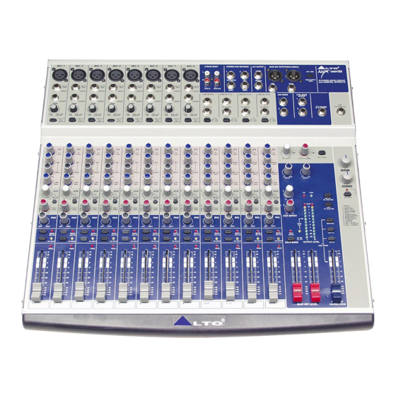
4. CONTROL ELEMENTS AMX-220 MIC 1 MIC 2 MIC 3 MIC 4 MIC 5 MIC 6 MIC 7 MIC 8 2-TRACK IN/OUT STEREO AUX RETURNS ALT OUTPUT MAIN MIX OUTPUT(BAL/UNBAL) -220 LEFT(3) LEFT(3) MIC +4dBu MIC +4dBu MIC +4dBu MIC +4dBu J.T. - Page 9 AMX-220FX MIC 1 MIC 2 MIC 3 MIC 4 MIC 5 MIC 6 MIC 7 MIC 8 2-TRACK IN/OUT STEREO AUX RETURNS ALT OUTPUT MAIN MIX OUTPUT(BAL/UNBAL) -220 LEFT(3) LEFT(3) MIC +4dBu MIC +4dBu MIC +4dBu MIC +4dBu J.T. J.T.
-
Page 10: Mono Mic/Line Channels
4.1 MONO MIC/LINE CHANNELS These are channel 1 through channel 8. You can connect balanced, MIC 1 low impedance microphones or a low level signal to the XLR socket. On the 1/4" line jack you can connect either a microphone or a line level instrument such as synthesizers, drum machines, effect pro- J.T. -
Page 11: Equalizer
4.7 EQUALIZER The mono input channels (channel 1~8) are equipped with 3-band MID sweep EQ: HI band, MID band and LOW band. And the stereo channels (channel 9~16) are equipped with 4-band fixed frequency 12kHz 12kHz EQ: HI band, HI-MID band, MID-LOW band and LOW band. All bands provide up to 15dB boost or cut. -
Page 12: Peak Led
Note: in AMX-220FX, the returned signal of AUX RETURN1 will also be routed to AUX RETURN if there is no signal feeding to AUX RETURN 2 sockets. The signal is summed,on mixed in to the main L/R mix bus. -
Page 13: Aux Sends
4.21 PHONES This socket will send out the mix signal to a pair of headphones. 4.22 DSP FOOTSWITCH (for AMX-220FX model only) This socket is used to connect external footswitch for your convenient operation, it will activate/ deactivate the DSP module in this unit and function same as DFX MUTE switch 4.23 AUX RETURN CONTROL... -
Page 14: Output Level Led Display
This LED indicates when the phantom power is switched on. 4.30 POWER LED This LED indicates when the power is on in your AMX-220/AMX-220FX. 4.31 SOLO MODE SWITCH This button provides two modes: up for PFL (Pre-Fader-Listen) mode,down for AFL(After-Fader-Listen) mode. -
Page 15: Rear Panel Description
This switch will apply +48 Volt Phantom Power only to the 8 XLR microphone inputs. Never connect microphones When the phantom power is on already. - AC INPUT CONNECTOR This connector is used to connect the 18VAC adapter supplied by LTO company only. -
Page 16: Installation And Connection
5. INSTALLATION AND CONNECTION Ok, you have got to this point and you are now in the position to successfully operate your AMX-220/AMX-220FX. However, we advise you to read carefully the following section to be the real master of your own mixer. Not paying... - Page 17 5.1 Some Final Tips on Wiring Configuration You can connect unbalanced equipment to balanced inputs and outputs. Simply follow these schemes. Ring=Right Signal Sleeve Ring Strain Clamp Tip=Left Signal Sleeve=Ground/Screen Use for Headphone, Stereo Return 1/4" Stereo (TRS) Jack Plug Sleeve Tip=Signal Strain Clamp...
- Page 18 Ring=Return Signal (Connected together) To Channel Insert Sleeve=Ground/Screen Tip=Signal To Tape or FX Input Sleeve=Ground/Screen 'Tapped' Connection Direct Output Lead (Enables the Insert to be used as a Direct Output while maintaining the channel signal flow) To Processor Input Sleeve=Ground/Screen Tip=Send Signal To Channel Insert Ring=Return Signal...
-
Page 19: For The Experts Who Want To Know More
6. FOR THE EXPERTS WHO WANT TO KNOW MORE As we have told you previously in this manual, the AUX SEND2 control both on mono and on stereo channels is factory wired as POST-FADER. If you have some skill in electronic components soldering you can modify this setting and have all your AUX SENDS configured as PRE-FADER. -
Page 20: Preset List
7. PRESET LIST (For AMX-180FX Model) 01. VOCAL1 Pre-delay Rev. Type Hi Damp Rev Time Room Size 1.00 Hall Tape 1.00 Spring 4.50 3.60 Plate Spring 1.20 3.60 Hall Plate 1.50 Plate Spring 2.40 Tape 0.90 1.50 Plate 1.00 Hall Spring 1.00 Tape... - Page 21 4.00 -0.96 4.00 -12.00 4.00 -0.96 4.00 -12.00 3.60 -0.96 3.60 -12.00 3.60 -0.96 3.60 -12.00 04. SMALL HALL Pre-delay Hi Damp Rev Time Room Size Rev level 2.90 -0.96 2.90 -12.00 2.90 -0.96 2.90 -12.00 2.10 -0.96 2.10 -12.00 2.10 -0.96 2.10...
- Page 22 06. SMALL ROOM Pre-delay Hi Damp Rev Time Room Size Rev level 2.10 -0.96 2.10 -12.00 2.10 -0.96 2.10 -12.00 1.50 -0.96 1.50 -12.00 1.50 -0.96 1.50 -12.00 1.00 -0.96 1.00 -12.00 1.00 -0.96 1.00 -12.00 0.70 -0.96 0.70 -12.00 0.70 -0.96 0.70...
- Page 23 3.60 -0.96 3.60 -12.00 2.90 -0.96 2.90 -12.00 2.10 -0.96 2.10 -12.00 1.30 -0.96 1.30 -12.00 09. SPRING REVERB Pre-delay Hi Damp Rev Time Room Size Rev level -0.96 -12.00 4.50 -0.96 4.50 -12.00 -0.96 -12.00 3.60 -0.96 3.60 -12.00 2.90 -0.96 2.90...
- Page 24 11. STEREO DELAY Delay Right Delay Left F.B. Right F.B. 12. FLANGER Mod. Freq Pitch. Depth Left F.B. Right F.B. 2.79 2.52 2.33 2.25 2.10 1.99 1.75 1.61 1.34 1.22 1.00 0.80 0.65 0.54 0.42 0.16 13. CHORUS Mod. Freq. Pitch.
- Page 25 2.33 -3(0) 1.99 -3(0) 1.70 -3(0) 1.35 -2(0) 1.00 -2(0) 0.50 -2(0) 14. REVERB+DELAY Rev Time Room Size Left Delay Right Delay Left F.B. Right F.B. Rev level 2.90 2.90 2.90 2.90 2.40 2.40 2.40 2.40 2.10 2.10 1.50 1.50 1.50 1.50 1.00...
- Page 26 16. REVERB+CHORUS Rev Time Room Size Mod. Freq. Pitch. Depth Left F.B. Rev level 2.90 4.74 2.90 4.12 2.90 3.67 2.90 3.02 2.90 2.63 2.90 1.99 2.90 1.35 2.90 0.50 1.50 4.74 1.50 4.12 1.50 3.67 1.50 3.02 1.50 2.63 1.50 1.99 1.00...
-
Page 27: System Block Diagram
8. SYSTEM BLOCK DIAGRAM SEND LOGIC LOGIC SEND SEND SOLO(PFL) SOLO(PFL) AFL-R AFL-R AFL-L AFL-L AUX-2 AUX-2 AUX-1 AUX-1 ALT-4(R) ALT-4(R) ALT-3(L) ALT-3(L) HT-B HT-B LEFT-BUS LEFT-BUS... -
Page 28: Technical Specification
OFF to +15dB AUX Sends max out +22dBu Power supply Main voltage USA/ Canada 100-120V~,60Hz (AC/AC Adaptor) Europe 210-230V~,50Hz U.K/Australia 240V~,50Hz Power Consumption 22watts Physical Dimension (W D H) 427mm 412mm 43mm Net weight 5.90kg for AMX-220 5.98kg for AMX-220FX... -
Page 29: Warranty
10. WARRANTY 10.1 WARRANTY REGISTRATION CARD To obtain Warranty Service, the buyer should first fill out and return the enclosed Warranty Registration Card within10 days of the Purchase Date. All the information presented in this Warranty Registration Card gives the manufacturer a better understanding of the sales status, so as to purport a more effective and efficient after-sales warranty service. - Page 30 SEKAKU ELECTRON INDUSTRY (H.K.) CO. LTD. No.1, Lane 17, Sec. 2, Han Shi West Road, Taichung, 401 TAIWAN http://www.altoproaudio.com Tel:886-4-22313737 email: alto@altoproaudio.com Fax:886-4-22346757 All rights reserved to ALTO. All features and content might be changed without prior notice. Any photocopy, translation, or reproduction of part of this manual without written permission is forbidden.
Need help?
Do you have a question about the AMX-220FX and is the answer not in the manual?
Questions and answers