Table of Contents
Advertisement
Quick Links
Advertisement
Table of Contents

Related Manuals for Tyco Mastr III

Summary of Contents for Tyco Mastr III
- Page 1 Installation Manual LBI-38636S MASTR ® Conventional Base Station...
- Page 2 LBI-38636S NOTE Repairs to this equipment should be made only by an authorized service technician or facility designated by the supplier. Any repairs, alterations or substitution of recommended parts made by the user to this equipment not approved by the manufacturer could void the user’s authority to operate the equipment in addition to the manufacturer’s warranty.
-
Page 3: Table Of Contents
LBI-38636S TABLE OF CONTENTS Page PRODUCT SPECIFICATION FOR CE MARKED EQUIPMENT ..................5 MAXIMUM PERMISSIBLE EXPOSURE (MPE) LIMITS....................6 DETERMINING MPE RADIUS............................6 SAFETY TRAINING INFORMATION ..........................6 STATION SPECIFICATIONS (GENERAL)........................8 PUBLICATIONS INDEX ..............................9 SAFETY SUMMARY..............................11 GROUND THE EQUIPMENT.............................11 REPLACEMENT OF PLUG-IN CIRCUIT MODULES .....................11 ELECTROSTATIC DISCHARGE - SENSITIVE COMPONENTS................11 DO NOT SUBSTITUTE PARTS OR MODIFY PRODUCT..................12 INTRODUCTION ................................12... -
Page 4: Product Specification For Ce Marked Equipment
The MASTR III Base Station and Auxiliary Receiver may be used in both trunked and conventional applications. Neither the MASTR III Base Station nor the Auxiliary Receiver may be connected to leased lines in Europe without an additional line- barrier protection device. -
Page 5: Maximum Permissible Exposure (Mpe) Limits
LBI-38636S MAXIMUM PERMISSIBLE EXPOSURE (MPE) LIMITS Do not transmit with this basestation and antenna when persons are within the MPE Radius of the antenna. The MPE Radius is the minimum distance from the antenna axis that ALL persons should maintain in order to avoid RF exposure higher than the allowable MPE level set by the FCC. - Page 6 LBI-38636S • American National Standards Institute (C95.3 – 1992), IEEE Recommended Practice for the Measurement of Potentially Hazardous Electromagnetic Fields – RF and Microwave. TO ENSURE THAT YOUR EXPOSURE TO RF ELECTROMAGNETIC ENERGY IS WITHIN THE FCC ALLOWABLE LIMITS FOR OCCUPATIONAL USE, ALWAYS ADHERE TO THE FOLLOWING GUIDELINES: DO NOT operate the basestation with an antenna that would cause an ERP in excess of that CAUTION...
-
Page 7: Station Specifications (General)
LBI-38636S STATION SPECIFICATIONS (GENERAL) CABINET 37-INCH 69-INCH Height 37.0 inches 69.1 inches Width 21.5 inches 23.1 inches Depth 18.25 inches 21.0 inches Weight (note 1) 150 lbs (68 kg) Rack Units (RU) (note 2) Cabinet capacity 17 RU 33 RU Radio 8 RU 8 RU... -
Page 8: Publications Index
LBI-38636S PUBLICATIONS INDEX MASTR III BASE STATION Systems Combination Package .............. LBI-38775 T/R Shelf ............................LBI-38637 System Module..........................LBI-38764 LBI-39176 Power Module ..........................LBI-38752 MASTR III PC Programmer........................TQ-3353 MASTR III Installation Manual ......................LBI-38636 RF Module Test Fixture ......................... LBI-38805 MASTR III Utility Handset........................ - Page 9 LBI-38636S NOTE: Indented maintenance manuals are included with the header (cover) maintenance manual.
-
Page 10: Safety Summary
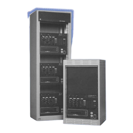
LBI-38636S Figure 1 - Typical 37-inch MASTR III Stations REPLACEMENT OF PLUG-IN CIRCUIT SAFETY SUMMARY MODULES The following general safety precautions must be Component or module replacement and internal observed during all phases of operation, service, and adjustments must be made by qualified maintenance repair of this product. -
Page 11: Do Not Substitute Parts Or Modify Product
INTRODUCTION SITE PREPARATION AND This manual describes installation connections for a typical MASTR III station combination. INSTALLATION Information provided includes suggested locations and installation of equipment and hardware, interconnection CABINET INSTALLATION and assembly diagrams, alignment instructions, and troubleshooting suggestions. -
Page 12: Double Stacked 37-Inch Cabinet Installation
Double Stacked 37-inch Cabinet installation For limited floor space situations, two 37-inch MASTR III cabinets may be stacked one upon the other. This requires that the bottom cabinet be securely bolted to the floor surface and the top cabinet securely bolted to the Figure 4 - Stacked 37-Inch Cabinets top surface of the bottom cabinet, as shown in Figure 4. -
Page 13: Electrical Connections
LBI-38636S ELECTRICAL CONNECTIONS TELEPHONE LINE CHARACTERISTICS Telephone Lines AC Power The type of telephone lines required for the The station will be received with the power cord installation will depend on how the station is controlled bundled and stored in the bottom of the cabinet. Remove and if it is being used for simplex or duplex operation. -
Page 14: Figure 6 - T/R Shelf Connections
LBI-38636S less populated areas where the phone company has not yet problems on DC systems since only the voice peaks are switched to carrier systems. These lines have a fixed clipped. However, special care must be used when amount of loss, which varies with frequency, temperature, applying them to tone remote control systems. - Page 15 LBI-38636S...
-
Page 16: Tone Remote Control Systems
LBI-38636S The telephone company wants to see a maximum three- The loss between 500 and 2500 Hz can be +2 dB and second level of -13 dBm at the carrier equipment as -8 dB relative to 1000 Hz loss. Note that the phone man measured on a modified Western Electric 3-type Noise may refer to this as -2 and +8 in the telephone company Measuring Set. -
Page 17: Voting System Considerations
LBI-38636S 2. The loss of the circuit at 2175 Hz. Do not forget selector 3 dB lower than the 1000 Hz test tone level. Most the long-term variation of up to 4 dB more. telephone lines have a frequency response which attenuates the 1950 Hz tone with respect to a 1000 Hz test 3. -
Page 18: Telephone Company Ordering Information
LBI-38636S Telephone Company Ordering Information Four-Wire Operation When ordering a telephone line, the following must For examples, refer to Methods 3 and 4 in Table 1, be considered: and the associated illustrations showing the different 1. Type of circuit: methods (Figures 10 & 11). Jumpers should be installed Voice grade, 2-wire termination, for radio on P104-2 to P104-3 and P105-2 to P105-3 on the control, and tone remote system - send/... -
Page 19: Tone Remote Installation
LBI-38636S Tone Remote Installation Four Wire Tone Remote Jumpers P104 and P105 located on the Interface When the control shelf is used with a four wire tone Board are not required and should be removed. Refer to re-mote/console, the remote control transmit pair (which sections TELEPHONE LINE... -
Page 20: Figure 7 - Typical E & M Signaling Application
LBI-38636S Table 1 - Wire Line Installation Methods METHOD DESCRIPTION PROCEDURE ADVANTAGES OR DISADVANTAGES Single metallic pair (the a. Connect the metallic pair to Economical: Dependable where earth control currents TB101-3 and -4. ground currents may be large or good simplexed to line, a two earth grounds cannot be obtained. -
Page 21: Figure 8 - Method 1 (Single Metallic Pair)
LBI-38636S Figure 8 - METHOD 1 (Single Metallic Pair) Figure 9 - METHOD 2 (Single Metallic, Earth Ground) -
Page 22: Figure 10 - Method 3 (Metallic Control Pair, Audio Pair)
LBI-38636S Figure 10 - METHOD 3 (Metallic Control Pair, Audio Pair) Figure 11 - METHOD 4 (Full Duplex Metallic TX Pair) -
Page 23: Station Setup
(TB101). Use the STATION SETUP following information when making connections: The MASTR III station comes pre-programmed and TB101, Pins 3,4 - Line Input/Output for 2-wire ready to install, the only adjustments needed are the DC and Tone control. -
Page 24: Figure 14 - Antenna Installation
LBI-38636S Table 3 - Station Connectors CONFIGURATION STATION TERMINATING LOCATION CONNECTOR Simplex (T/R Relay) N-Type Female Antenna Switch Duplex (Internal Duplexer) N-Type Female Duplexer Duplex (External Duplexer) BNC Female (Rx) T/R Shelf N-Type Female (Tx) Low Pass Filter TO ENSURE THAT YOUR EXPOSURE TO RF ELECTROMAGNETIC ENERGY IS WITHIN THE FCC ALLOWABLE LIMITS FOR OCCUPATIONAL USE, ALWAYS ADHERE TO THE FOLLOWING GUIDELINES: DO NOT operate the basestation with an antenna that would cause an ERP in excess of that... -
Page 25: Alignment Procedure
Table 4 - Normal System Deviation ALIGNMENT PROCEDURE System Deviation Standard (25 Hz kHz Bandwidth 3.0 kHz Alignment of the MASTR III base station was NPSPAC 2.4 kHz performed prior to shipment. The factory assumed the Narrow (12.5 kHz Bandwidth) 1.5 kHz... -
Page 26: Figure 15 - Mastr Iii System Module Pot Alignment
Adjust RG pot for 60% of system deviation Input and the REMOTE PTT. (Table 8). • Repeat this step for every channel. Figure 15 - MASTR III System Module Pot Alignment Table 7 - Digital Potentiometer Settings Line DSP Line Line... - Page 27 LBI-38636S 5. Line Input Sensitivity and Compression 6. Line Out • • If not a remote station, set the DSP Line In If not a remote station, set the Line Out LO DLI Pot to 0. Pot to 0. • •...
-
Page 28: Audio Routing And Adjustments
LBI-38636S U15 selects, which audio source is routed to the AUDIO ROUTING AND transmitter. Possible sources are LOCAL MIC, REPEAT ADJUSTMENTS AUDIO, DSP LINE/TX AUDIO, DSP TX AUDIO, EXTERNAL High Speed Data, LINE IN AUDIO, OPEN Once the T/R Shelf is installed and programmed (used for Morse code ID), and GROUND (used for no properly, audio level adjustments may be made for proper transmission. - Page 29 LBI-38636S...
- Page 30 LBI-38636S...
-
Page 31: Figure 16 - T/R Shelf Interface Board
LBI-38636S Figure 16 - T/R Shelf Interface Board... - Page 32 LBI-38636S...
- Page 33 LBI-38636S...
-
Page 34: Figure 17 - T/R Shelf Interface Board (Rev. A)
LBI-38636S Figure 17 - T/R Shelf Interface Board (Rev. A) - Page 35 LBI-38636S...
- Page 36 LBI-38636S...
-
Page 37: Figure 18 - T/R Shelf Interface Board ( Rev. C)
LBI-38636S Figure 18 - T/R Shelf Interface Board ( Rev. C) -
Page 38: Remote Controller To Station Control Panel Adjustments
GROUND (used for no transmission, and LINE IN audio (used for four wire loop around). A battery the MASTR III backplane at J5, Pin 28A. alarm tone and/or VG ALERT tone may also be summed in with whichever source is selected with the exception of If four wire audio is used, the DSP line cancellation GROUND. -
Page 39: Repeater Panel Installation
NOTE Subaudible Tone Modulation level. Use the following information in Table 11 to configure the MASTR III base station when installing the CSI-32 Repeater Panel. Zetron 38A Repeater Panel 1. Cut the PWB pattern at JP-1 on the T/R Shelf’s backplane 19D902948. - Page 40 LBI-38636S Table 11 - CSI-32 Repeater Panel Connections CSI-32 MASTR III SIGNAL NAME FUNCTION CONNECTION Pin 1 A+/(DC Power) P5.1 Pin 2 SYS_VOL \SQ_HI/Repeat Audio) P5.8 Pin 3 RCVR_VOL\SQ_HI/ (Demodulated Audio) P2.5 Pin 4 Pin 5 REPEAT_PTT_IN P2.13 Pin 6 CAS/(Carrier Activated Squelch) P3.5...
-
Page 41: Accessories
LBI-38636S ACCESSORIES The following accessories for the MASTR III Station may be obtained from your local dealer or by calling M/A-COM After Market Services 24- hour Toll Free Number 1-800-368-3277 (USA only) or FAX 1-800-833-7592. Please provide the description and part number or package number when ordering. - Page 42 LBI-38636S This Page Intentionally Blank...
- Page 43 INTERCONNECTION DIAGRAM LBI-38636S MASTR III STATION T/R SHELF INTERCONNECT (19D903635, Sh. 1, Rev. 4A)
- Page 44 LBI-38636S INTERCONNECTION DIAGRAM MASTR III STATION MASTR III STATION ANTENNA CONFIGURATION INTERCONNECT AUXILIARY RECEIVER INTERCONNECT (19D903635, Sh. 2, Rev. 6) (19B802439, Rev. 1)
- Page 45 INTERCONNECTION DIAGRAM LBI-38636S MASTR III STATION EMERGENCY POWER INTERCONNECT 19D903635, Sh. 3, Rev. 2)
- Page 46 LBI-38636S INTERCONNECTION DIAGRAM MASTR III STATION GETC/VG INTERCONNECT (19D904268, Rev. 4)
- Page 47 INTERCONNECTION DIAGRAM LBI-38636S MASTR III STATION SCAT (188D5683, Rev. 2)
- Page 48 LBI-38636S INTERCONNECTION DIAGRAM MASTR III STATION MASTR III STATION BACK-TO-BACK REPEATER BACK-TO-BACK REPEATER HARNESS (19B804016, Rev. 1) (19B803976, Rev. 1)
- Page 49 LBI-38636S (Intentionally Left Blank)
- Page 50 M/A-COM Wireless Systems 3315 Old Forest Road Lynchburg, Virginia 24501 (Outside USA, 434-385-2400) Toll Free 800-528-7711 www.macom-wireless.com Printed in U.S.A.
Need help?
Do you have a question about the Mastr III and is the answer not in the manual?
Questions and answers