Table of Contents
Advertisement
Quick Links
Advertisement
Table of Contents
Troubleshooting

Related Manuals for Vaisala HydroMet

Summary of Contents for Vaisala HydroMet
- Page 1 USER'S GUIDE Vaisala HydroMet™ Data Collection Platform Volume 1 M210784EN-E...
- Page 2 The contents are subject to change without prior notice. Please observe that this manual does not create any legally binding obligations for Vaisala towards the customer or end user. All legally binding commitments and agreements are included exclusively in the...
-
Page 3: Table Of Contents
Lizard Setup Software ......33 Updating QML Software ......34 VAISALA ________________________________________________________________________ 1... - Page 4 User’s Guide ______________________________________________________________________ CHAPTER 3 AWS CLIENT SOFTWARE ........35 Product Overview .
- Page 5 GLOSSARY ..........153 VAISALA ________________________________________________________________________ 3...
- Page 6 User’s Guide ______________________________________________________________________ 4 ____________________________________________________________________M210784EN-E...
-
Page 7: List Of Figures
Setup File Download Progress View ....84 Figure 45 Starting Logger Content Cleanup ..... . 84 VAISALA ________________________________________________________________________ 5... - Page 8 User’s Guide ______________________________________________________________________ Figure 46 Output of Logshow Command ......86 Figure 47 Output of the Logstatus Command .....88 Figure 48 List of Log Files Available for Downloading .
-
Page 9: List Of Tables
QML201C Logger Accuracy Specifications ....151 Table 40 QML201C Logger Regulatory Compliances ....152 VAISALA ________________________________________________________________________ 7... - Page 10 User’s Guide ______________________________________________________________________ 8 ____________________________________________________________________M210784EN-E...
-
Page 11: Chapter 1 General Information
This manual is applicable for data logger QML201C and AWS Client software version 7.00. For more detailed and advanced information on data collection software and telemetry, refer to the supplementary user manuals Vaisala HydroMet™ Data Collection Platform User’s Guide, Volumes 2 and 3. VAISALA ________________________________________________________________________ 9... -
Page 12: Structure Of The Data Collection Platform Documentation
User's Guide ______________________________________________________________________ Structure of the Data Collection Platform Documentation The information in the Vaisala HydroMet™ Data Collection Platform manual set is divided between the different manuals in the documentation set as outlined in Table 1 on page Table 1... -
Page 13: Version Information
First version of this manual. Related Manuals Table 3 Related Manuals Manual Code Manual Name M210785EN Vaisala HydroMet™ Data Collection Platform User's Guide, Volume 2 M210933EN Vaisala HydroMet™ Data Collection Platform User's Guide, Volume 3 M210786EN Vaisala HydroMet™ Data Collection Platform... -
Page 14: Documentation Conventions
User's Guide ______________________________________________________________________ Documentation Conventions Throughout this manual, important safety considerations are highlighted as follows: WARNING Warning alerts you to a serious hazard. If you do not read and follow instructions very carefully at this point, there is a risk of injury or even death. -
Page 15: Product-Related Safety Precautions
Do not substitute parts or modify the instrument. Because of the danger of introducing additional hazards, do not install unsuitable parts in the instrument. Contact Vaisala or its authorized representative for repairs to ensure that safety features are maintained. VAISALA _______________________________________________________________________ 13... -
Page 16: Esd Protection
ESD Protection Electrostatic Discharge (ESD) can cause immediate or latent damage to electronic circuits. Vaisala products are adequately protected against ESD for their intended use. However, it is possible to damage the product by delivering electrostatic discharges when touching, removing, or inserting any objects inside the equipment housing. -
Page 17: Recycling
United States and/or other countries. License Agreement All rights to any software are held by Vaisala or third parties. The customer is allowed to use the software only to the extent that is provided by the applicable supply contract or Software License Agreement. -
Page 18: Redistribution License Agreement
User's Guide ______________________________________________________________________ Redistribution License Agreement The QML logger software uses the TCP/IP stack produced by the "lwIP Lightweight TCP/IP stack" -project with the following copyright and license: Copyright © 2001, 2002 Swedish Institute of Computer Science. All rights reserved. Redistribution and use in source and binary forms, with or without modification, are permitted provided that the following conditions are met:... -
Page 19: Warranty
Chapter 1 ________________________________________________________ General Information Warranty For certain products Vaisala normally gives a limited one-year warranty. Please observe that any such warranty may not be valid in case of damage due to normal wear and tear, exceptional operating conditions, negligent handling or installation, or unauthorized modifications. - Page 20 User's Guide ______________________________________________________________________ 18 ___________________________________________________________________M210784EN-E...
-
Page 21: Chapter 2 Product Overview
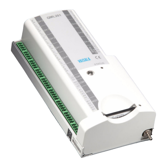
Chapter 2 __________________________________________________________ Product Overview CHAPTER 2 PRODUCT OVERVIEW This chapter introduces the basic data collection hardware and software. Data Collection Hardware QML Logger Figure 1 QML Logger 1005-064 VAISALA _______________________________________________________________________ 19... - Page 22 User's Guide ______________________________________________________________________ The QML logger is a complete AWS data logger designed on one printed board only. This board contains a 32-bit Motorola CPU for data processing and 10 differential (20 single-ended) analog sensor inputs (these can also be used as digital inputs). Moreover, there are two frequency sensor interfaces, a 24-bit A/D converter, 3.3 MB of secure Flash memory for data logging, as well as an excitation power supply for sensors and a charger for the internal backup battery.
-
Page 23: Figure 2 Qml Logger Without Cover
QML Logger without Cover 1004-120 The following numbers refer to Figure 2 on page Pressure sensor connector Communication module places MOD1 and MOD2 SPI connector Status LED (green) Lithium battery for RTC Reset button CF Card connector VAISALA _______________________________________________________________________ 21... -
Page 24: Qml Logger Connector Block
PCMCIA reader as well as external readers to be connected to USB or parallel port of a PC. You are recommended to only use cards purchased from Vaisala that have been tested to function in harsh environments. Figure 3... -
Page 25: Table 4 Analog Measurement Channels
0 ... 12 V/20 mA adjustable excitation input signals 12-bit voltage, can be measured. Fast analog input (High) Fast analog input (Low) Common return (Analog ground) Table 5 Power Channels Pin Name Description Ground SDI-12 SDI-12 Ground +ExtDC 8 ... 30 VDC VAISALA _______________________________________________________________________ 23... -
Page 26: Figure 4 Connector Blocks
User's Guide ______________________________________________________________________ Figure 4 Connector Blocks 1003-029 24 ___________________________________________________________________M210784EN-E... -
Page 27: Accessories
NOTE The multiplexer unit makes only analog measurements. NOTE The multiplexer unit can only be connected to the QML201 logger or newer. The type of the logger can be checked with the VER command. VAISALA _______________________________________________________________________ 25... -
Page 28: Digital I/O Module
User's Guide ______________________________________________________________________ Digital I/O Module Figure 6 Digital I/O Module QMI118 1004-041 The QML logger provides the possibility to extend the I/O capacity with the optional digital I/O module (QMI) equipped with eight inputs and eight outputs. The digital I/O module interfaces to the logger via the SPI connector. -
Page 29: Transient Protection Devices
These are easy to change in the field without tools. Figure 7 Surge Protector for Serial Lines 0802-050 Optional coaxial surge protectors can be used for UHF and VHF antennas as well as for the RF signal input when radio or satellite equipment is used. VAISALA _______________________________________________________________________ 27... -
Page 30: Communication Modules
User's Guide ______________________________________________________________________ Communication Modules RS-232 Module The RS-232 communication module is unisolated, providing either a double serial channel without handshaking (dual RS-232 module) or a single RS-232 with handshaking (single RS-232 module). The power consumption is less than 15 mA when communicating, less than 5 mA at standby. -
Page 31: Dual-Isolated Rs-485 Communication Module
The RS-232 mode utilizes channel B. When channel B is used in the RS-232 mode, it is possible to use channel A as a galvanically isolated two-wire RS-485 channel. The RS-232 channel is galvanically connected to the host board's GND potential. VAISALA _______________________________________________________________________ 29... -
Page 32: Fixed Line Modem Module
Fixed Line Modem Module The fixed line modem module is used for providing a long-distance fixed line connection between two Vaisala devices with a similar interface. It is used when the distance is up to 10 km, for example, between the QML logger and a digital display, or between a ceilometer and the logger. -
Page 33: Ethernet Communication Module Dse101
Because DSE101 always transmits data at 10 Mbps, the connecting switch or router must not be locked to 100 Mbps or faster speed. DSE101 requires version 6.01 of MAWS software or higher to operate. VAISALA _______________________________________________________________________ 31... -
Page 34: Data Collection Software
AWS Client software. AWS Client Software Vaisala AWS Client software is used for downloading data log files, issuing QML logger commands and setting its parameters, and performing maintenance tasks on the QML logger. The supported connection types to the QML logger are serial line, dial-up connections using a modem, and TCP/IP socket connections. -
Page 35: Setup Software
Generate functionality to create a setup file that contains all the information. The setup file is then transferred into the logger using AWS Client software. For more detailed information, refer to Vaisala HydroMet™ Data Collection Platform User’s Guide, Volumes 2 and 3. VAISALA _______________________________________________________________________ 33... -
Page 36: Updating Qml Software
Updating QML Software The QML logger software may need to be updated in order for you to utilize new features published by Vaisala. CAUTION Update the QML logger software only when requested by Vaisala. Please contact Vaisala for further instructions. 34 ___________________________________________________________________M210784EN-E... -
Page 37: Chapter 3 Aws Client Software
Automatic Weather Station Client, or AWS Client for short, for working with the QML logger. Product Overview Vaisala AWS Client is used for downloading data log files, issuing QML logger commands and setting its parameters, and performing maintenance tasks on the QML logger. The supported connection types to the QML logger are serial line, dial-up connections using a modem, and TCP/IP socket connections. -
Page 38: Installing Aws Client
User's Guide ______________________________________________________________________ With AWS Client, you can convert the data log files into CSV format for viewing in other applications, such as Microsoft Excel. You can define several download settings, such as an automatic download schedule, where you want to save the downloaded files, and what operations the program performs automatically at each download. -
Page 39: Installation Procedure
Next. Figure 13 Installation Wizard Welcome Window 0802-043 The License Agreement window shown in Figure 14 on page 38 is displayed next. Read the license agreement and accept it. Select Next to continue the installation. VAISALA _______________________________________________________________________ 37... -
Page 40: Figure 14 License Agreement Window
User's Guide ______________________________________________________________________ Figure 14 License Agreement Window 0802-046 The Select Installation Folder window is displayed next as shown Figure 15 on page 39. To install the AWS Client software in the default installation folder, select Next. You can also change the installation folder on your desktop computer by selecting Browse and then browsing for the folder you want or by entering the installation folder path in the Folder field. -
Page 41: Figure 15 Select Installation Folder Window
Chapter 3 _______________________________________________________ AWS Client Software Figure 15 Select Installation Folder Window 0802-044 The Ready to Install window is displayed as shown in Figure 16 on page 39. Start the installation by selecting Install. Figure 16 Ready to Install Window 0802-045 VAISALA _______________________________________________________________________ 39... -
Page 42: Figure 17 Installation Complete Window
Exit the installation wizard by selecting Finish. Figure 17 Installation Complete Window 0802-047 After installation, you can access the AWS Client software via the Vaisala program group in the All Programs list in the Windows Start menu. 40 ___________________________________________________________________M210784EN-E... -
Page 43: Establishing Terminal Connection
Opening Service Connection on page Open the service connection by selecting Terminal Connect on the Maintenance menu or by clicking the Open command mode button on the toolbar. Figure 19 on page 42 shows the pin order for the terminal connector. VAISALA _______________________________________________________________________ 41... -
Page 44: Figure 19 Terminal Connector Com0 Pins
User's Guide ______________________________________________________________________ Figure 19 Terminal Connector COM0 Pins 0304-025 The following numbers refer to Figure 19 on page Not connected Not connected 42 ___________________________________________________________________M210784EN-E... -
Page 45: Using Aws Client Software
Using AWS Client Software Starting and Exiting AWS Client You can start AWS Client by clicking the Start button and then selecting Programs - Vaisala - AWS Client. AWS Client is opened with the terminal main window shown in Figure 20 on page... -
Page 46: Aws Client Main Window
User's Guide ______________________________________________________________________ Figure 21 Terminal Showing Report 0802-135 NOTE The report type and appearance shown in Figure 21 on page 44 depend on your setup. You can exit AWS client by selecting the Exit option from the File menu. AWS Client Main Window On top of the main window, you can find the AWS Client toolbar. -
Page 47: Defining Aws Client Settings
Address Book The AWS Client Address Book, shown in Figure 22 on page 46, is used for storing and maintaining information on connections and their VAISALA _______________________________________________________________________ 45... -
Page 48: Serial Line Connections
User's Guide ______________________________________________________________________ parameters. The connection parameters to be configured depend on the connection type: serial line, dial-up connection, or TCP/IP socket connection. The following sections describe the parameters for each connection type. Figure 22 Address Book Window 0802-136 Serial Line Connections To add an Address Book entry for a serial line connection, proceed as follows: On the Settings menu, select Address Book. -
Page 49: Figure 23 Creating Serial Line Address Book Entry
If the request fails, a failure message is displayed instead, and you have the option to try again at a later time. Factors such as the current load on the logger, delays in the connection, and VAISALA _______________________________________________________________________ 47... -
Page 50: Tcp/Ip Socket Connections
Target IP and port settings match with AWS Client (server socket only) For further information, see section Virtual COM Port in Vaisala HydroMet™ Data Collection Platform User's Guide, Volume 3. If QML logger with DSE101 Ethernet piggyback does not have a valid setup but its IP address is known, it can be connected with a client socket connection to port 50000. -
Page 51: Figure 24 Creating Tcp/Ip Socket Connection Address Book Entry
AWS Client will wait for the logger to respond when AWS Client sends a requests over the TCP/IP connection. If the request, for instance, a log file download, succeeds within the timeout, a success message is VAISALA _______________________________________________________________________ 49... -
Page 52: Server Socket With Sms
GSM modem connected to the PC running the AWS Client software. For further information, see section IP Service Connectivity with GSM in Vaisala HydroMet™ Data Collection Platform User's Guide, Volume 3. To add an Address Book entry for a server socket connection with SMS, proceed as follows: On the Settings menu, select Address Book. -
Page 53: Figure 25 Creating Server Socket With Sms Address Book Entry
AWS Client will wait for the logger to respond when AWS Client sends a requests over the serial line connection. If the request, for instance, a log file download, succeeds within the timeout, a success message is VAISALA _______________________________________________________________________ 51... - Page 54 In the Port field, enter the port where the logger is configured to connect to. For further information, see section IP Service Connectivity with GSM in Vaisala HydroMet™ Data Collection Platform User's Guide, Volume 3. In the GSM Modem COM Port field, select the PC COM port where the GSM modem is connected to.
-
Page 55: Dial-Up Connections
Windows Dial-Up Networking entries is available in the window shown in Figure 26 on page Figure 26 Creating Dial-up Connection Address Book 0802-139 Entry In the Name field, enter an alphanumeric string that uniquely identifies the connection you are creating in the Address Book. VAISALA _______________________________________________________________________ 53... - Page 56 User's Guide ______________________________________________________________________ If you have multiple QML loggers on the same network and you are going to access them over the same dial-up connection, you need a unique identifier for each logger. To uniquely identify the logger for which you are creating an Address Book entry, enter a unique alphanumeric string in the Station id field.
-
Page 57: Options Window
English. Setup file download Default download directory for QML logger setup directory files. You can either enter the path for your directory or select Browse and browse for the directory. VAISALA _______________________________________________________________________ 55... -
Page 58: Table 8 Settings In Aws Client Options Window
User's Guide ______________________________________________________________________ Table 8 Settings in AWS Client Options Window (Continued) Setting Description Setup file upload Default upload directory for QML logger setup directory files. You can either enter the path for your directory or select Browse and browse for the directory. -
Page 59: Number Format
COM port manually. To establish a connection to the QML logger, select Connect from the File menu. You can also click the Open connection icon. The Address Book window is displayed as shown in Figure 28 on page VAISALA _______________________________________________________________________ 57... -
Page 60: Figure 28 Address Book Window
User's Guide ______________________________________________________________________ Figure 28 Address Book Window 0802-141 In the Address Book window, select the address book entry for the QML logger and click OK. To open the service connection, select Terminal Connect on the Maintenance menu or click the Open command mode button on the toolbar. -
Page 61: Giving Commands
To set new time, type for values example: time 15 45 00 To set new time and date, for example: time 15 45 00 07 06 18 loggo <group_id> Parameters shown in < > cannot be omitted. VAISALA _______________________________________________________________________ 59... -
Page 62: Closing Service Connection
User's Guide ______________________________________________________________________ NOTE Commands have to be typed in the same case as indicated in the help texts, usually in lower case. The command name and the following parameters are always separated by a space. Pressing ENTER (return) will execute the command so that the QML logger reads the typed command. -
Page 63: Managing User Levels
Setting a new or clearing an existing user level is effective only after a reset. When setting a new level or clearing an existing one, be sure to reset the system before closing the service connection. Otherwise, you may not be able to access the system without a cold reset. VAISALA _______________________________________________________________________ 61... -
Page 64: Table 10 Accessible Commands In Different User Levels
User's Guide ______________________________________________________________________ To check the allowed commands at a specific level, give the help command. Table 10 on page 62 lists the accessible commands in the different user levels. Level 1 provides access to the minimum set of commands and visibility of system parameters. Level 3 provides access to all commands needed for normal administration and commissioning. -
Page 65: Modifying Station Settings
QMB101 in Ah. Note that this value is set to zero when high capacity backup batteries are included in the delivery, which normally is the case with the HydroMet™ systems. If your QML logger does not include an internal battery, this field displays the text No battery. -
Page 66: Setting The Qml Logger Clock
User's Guide ______________________________________________________________________ Setting the QML Logger Clock With AWS Client, you can either set the clock and time zone of the QML logger manually, or you can synchronize the logger clock with the clock on your PC. To set the QML logger clock, proceed as follows: On the Maintenance menu, select Synchronize Clock. -
Page 67: Setting Static Parameters
QML logger static parameters can also be grouped into parameter sets. With parameter sets, you can group parameters belonging to a certain functionality together to be handled as a single entity. For more information on parameter sets, refer to the Vaisala HydroMet™ Data Collection Platform User’s Guide, Volume 3. NOTE All parameters are automatically created on the QML logger when the setup is uploaded. -
Page 68: Figure 31 Static Parameters Window
User's Guide ______________________________________________________________________ To change the value of a static parameter, proceed as follows: Start AWS Client and connect to the QML logger. On the Settings menu, select Parameters - Static. Expand the list for the parameter set whose parameters you want to change by clicking the plus sign next to the parameter set name. -
Page 69: Station Parameter Backup And Restore
Selecting File for Station Settings Backup 0906-065 Click Select File to start the backup. A file download progress dialog appears, and the backup is complete when AWS Client displays the following window: Figure 33 Parameter Backup Completed 0906-066 VAISALA _______________________________________________________________________ 67... -
Page 70: Figure 34 Selecting File For Station Settings Restore
User's Guide ______________________________________________________________________ To restore station settings backup with AWS Client, proceed as follows: Establish connection to the data logger. Open the Settings menu and choose Parameters and Restore to logger. In the file dialog, select the file containing the backup. Figure 34 Selecting File for Station Settings Restore 0906-067... -
Page 71: Calibrating Sensors
Calibration window. NOTE The Calibration window has no content for setups made with QML logger software versions prior to 3.06. With old setups, sensors need to be calibrated through the terminal connection with the appropriate calibration commands. VAISALA _______________________________________________________________________ 69... -
Page 72: Figure 36 Calibration Window
User's Guide ______________________________________________________________________ Figure 36 Calibration Window 0802-145 The available calibration methods are offset calibration and manual calibration. In offset calibration, you can change the offset value of the measurement by entering a new value for the sensor reading, and the offset value is changed accordingly. -
Page 73: Table 12 Fields In The Calibration Windows
New sensor calibration values are taken into use in the QML logger after a reset with, for example, the Reset command. For further information on resetting the QML logger, see section Resetting the QML Logger on page 103. VAISALA _______________________________________________________________________ 71... -
Page 74: Sensor Status List
User's Guide ______________________________________________________________________ Sensor Status List Table 13 Sensor Status List Value Description Notes Sensor is working properly (OK). Not measured yet. Interface is not initialized. Communication timeout has occurred. Unknown data is received. Communication is functioning, but the sensor reports errors. -
Page 75: Offset Calibration
Enter the new value for the measurement in the Value field and select Calibrate. The offset value for the measurement is adjusted accordingly: if, for example, you are calibrating a temperature measurement, and the value obtained from the sensor is 23 °C, VAISALA _______________________________________________________________________ 73... -
Page 76: Manual Calibration
User's Guide ______________________________________________________________________ entering 24 in the Value field will change the offset of the measurement to be 1 °C. NOTE The measurement values obtained from the sensors in the Offset Calibration view are not updated automatically. To get the latest measurement values, select the Refresh button. -
Page 77: Figure 38 Manual Calibration Window
The values you have changed in the Manual Calibration window but have not yet sent to the QML logger by selecting Calibrate are displayed in bold. You can obtain the current Offset and Factor values again from the QML logger by selecting the Refresh button. VAISALA _______________________________________________________________________ 75... -
Page 78: Entering Values For Manual Sensors
Client software, you must create and configure manual sensor(s) in Lizard Setup Software. For instructions on creating a manual sensor, see Chapter 3, Configuring Modules and Sensors, in Vaisala HydroMet™ Data Collection Platform User’s Guide, Volume 3. Viewing Manual Sensors in AWS Client For each manual sensor included in your setup, you can view information on the sensor’s status, the type of values for which the... -
Page 79: Figure 39 Manual Sensor Details
QML logger setup Maximum value Maximum accepted value for the manual sensor reading as configured in the QML logger setup Unit Unit for the manual sensor value You can close the manual sensor window by selecting Close. VAISALA _______________________________________________________________________ 77... -
Page 80: Entering Values For Manual Sensors
User's Guide ______________________________________________________________________ Entering Values for Manual Sensors With AWS Client, you can enter values for each manual sensor included in your QML logger setup. NOTE The values you enter for the manual sensors must match the manual sensor value type: Integer, Float, or Text. The Save button is disabled in the Manual Sensor window if the entered value is not of the correct type. -
Page 81: Setup File
However, this requires a thorough understanding of the system. For further information, refer to Vaisala HydroMet™ Data Collection Platform User's Guide, Volumes 2 and 3. CAUTION If you create a setup of your own by modifying the ready-made files, store the new file under a different name. -
Page 82: Uploading Setup File
User's Guide ______________________________________________________________________ CAUTION Also notice that the settings you define in the setup file must match the communication settings you make in the AWS Client Address Book and the station-specific settings for common and static parameters. Uploading Setup File CAUTION When you upload a new setup, the system erases all data log files from the QML logger. -
Page 83: Figure 41 Selecting An Upload Configuration File
Setup File Upload Progress window displayed. Figure 42 Setup Uplodad in Progress 0802-151 When the file has been transferred, the QML logger starts executing the new setup according to the settings in the setup file. VAISALA _______________________________________________________________________ 81... -
Page 84: Secure Setup Upload
User's Guide ______________________________________________________________________ Secure Setup Upload AWS Client can be configured to perform a secure setup upload sequence. This function attempts to keep a valid setup in the logger at all times, which minimizes the risk of the logger becoming inaccessible for remote maintenance if an error occurs while updating the setup. -
Page 85: Downloading Setup Files From Qml Logger
Select the folder to which the setup file is downloaded. The default folder is the one specified in the AWS Client Options window. Downloading the setup file from the QML logger starts; you can follow the download process in the window displayed (see Figure 44 on page 84). VAISALA _______________________________________________________________________ 83... -
Page 86: Aws Settings Cleanup
User's Guide ______________________________________________________________________ Figure 44 Setup File Download Progress View 0802-152 AWS Settings Cleanup To remove the settings of an earlier setup from the logger completely, AWS Client provides an automated function that performs a typical cleanup procedure. The function is available from menu Maintenance - AWS Cleanup. When started, the message in Figure 45 on page 84 is displayed. -
Page 87: Data Logging
(= log memory will be filled up completely). To ensure some data backup, for example, a value of 4 days is feasible. If the delete interval VAISALA _______________________________________________________________________ 85... -
Page 88: Log Data Format
User's Guide ______________________________________________________________________ is set negative with Lizard Setup Software, the old log files will not be deleted automatically. The approximate maximum logging period for a setup where 10 measured values are logged is shown in Table 15 on page Table 15 Log Memory Capacity Logging Interval... -
Page 89: Controlling Logging
To see the logging groups, type logstatus. To see the current logging status of a certain group, type logstatus <group_id>. To stop or start the logging of a certain group, type logstop/loggo <group_id>. For the output of the commands, see Figure 47 on page VAISALA _______________________________________________________________________ 87... -
Page 90: Measurement Enable Or Disable
User's Guide ______________________________________________________________________ Figure 47 Output of the Logstatus Command 0802-154 Measurement Enable or Disable You can manually enable or disable all measurement inputs and sensors. You can use this feature, for example, for the following purposes: Remotely changing the readings of a faulty sensor to be flagged as invalid. - Page 91 When the measurement input is disabled: All output values other than status have undefined values. Sensor status shows ; refer to the list of the sensor disabled statuses in Table 13 on page Value status shows INVALID NOT AVAILABLE VAISALA _______________________________________________________________________ 89...
-
Page 92: Freeing Up Logging Space
User's Guide ______________________________________________________________________ Freeing Up Logging Space A log file can be deleted with the logdel command: logdel <group_id> <lastdate (YYMMDD)> where logdel Command to delete log files belonging to certain log group group_id Name of the log group, that is, L0, L1, L2, or so on YYMMDD Date until which the log files will be deleted Example:... -
Page 93: Downloading Log Files
CTRL+A. Select the files you want to download by selecting the file name in the Select files to download list. If you decide not to download a file after all, you can remove its selection by clicking on the file name. VAISALA _______________________________________________________________________ 91... -
Page 94: Figure 49 Log File Download Settings Window
User's Guide ______________________________________________________________________ Select the folder for storing the downloaded log files by entering the path in the Log File Storage Directory field. You can also select Browse and then browse for the folder for storing the downloaded log files. To set your download options, select Settings. -
Page 95: Table 17 Log File Download Options
Close. The downloaded log files are located in the folder defined in the Log File Storage Directory field. VAISALA _______________________________________________________________________ 93... -
Page 96: Converting Downloaded Log Files To Csv Format
User's Guide ______________________________________________________________________ Figure 50 Log File Download Progress View 0802-157 Converting Downloaded Log Files to CSV Format You can use the CSV conversion functionality to convert log files downloaded to AWS Client in binary format to CSV format. NOTE The date and time formats in the converted log files depend on the date and time formats specified in the AWS Client language options. -
Page 97: Figure 51 List Of Log Files Available For Conversion
CTRL+A. If you decide not to convert a file after all, you can remove its selection by clicking on the file name. To set your conversion options, select Settings. The Log File Conversion Settings window shown in Figure 52 on page 96 displayed. VAISALA _______________________________________________________________________ 95... -
Page 98: Auto Downloading Log Files
User's Guide ______________________________________________________________________ Figure 52 Log File Conversion Settings 0803-163 The options available in the window and their use are described in Table 18 on page Table 18 Log File Conversion Options Option Description Merge log files of same Merges log files from different dates belonging to group the same log group. -
Page 99: Figure 53 Auto Download Settings Window
To enable auto-downloading, you must have AWS Client running continuously. In addition, if you are using a serial line connection, the COM port must be free and assigned for AWS Client. Figure 53 Auto Download Settings Window 0802-164 VAISALA _______________________________________________________________________ 97... -
Page 100: Table 19 Settings In Auto Download Settings Window
User's Guide ______________________________________________________________________ The options available in the window and their use are described in Table 19 on page Table 19 Settings in Auto Download Settings Window Option Description Address book entry Specifies the QML logger from which log files are to be downloaded. - Page 101 Stop downloading: Stops downloading the selected log files if a log file with the same name already exists in the log file download directory on your PC. Once you have set the schedule and other parameters, select Save. VAISALA _______________________________________________________________________ 99...
-
Page 102: Figure 54 Auto Download In Progress
User's Guide ______________________________________________________________________ The application waits in idle mode until polling is triggered. When polling, the application automatically opens a service connection to a station and downloads log files as defined by the user. During the download process, a progress dialog is displayed; see Figure 54 on page 100. -
Page 103: Viewing The Status Of Auto Downloads
Polling frequency value set for the download Logs From Time period from which logs are downloaded Completed Time of completion for the download Entry Station from which logs are downloaded File Count Number of log files downloaded Bytes Size of the download VAISALA ______________________________________________________________________ 101... -
Page 104: Using External Memory Card
User's Guide ______________________________________________________________________ Using External Memory Card The external memory card is used to store log files that have been copied or moved from the internal log directory. The data can be retrieved from the external memory card via terminal connection or by switching the memory card with an empty one. -
Page 105: Automatic Erase From External Memory Card
Figure 56 Delayed Reset Prompt 0802-165 In the Reset delay (s) field, enter the delay (in seconds) after which you want the logger to be reset. The logger reset will begin after the specified delay has elapsed. VAISALA ______________________________________________________________________ 103... -
Page 106: Reset Using The Reset Button
User's Guide ______________________________________________________________________ Select OK. The logger reset will start after the delay specified in the previous step. Once the reset is complete and the setup is running without problems, the AWS Client terminal window displays the text Setup running ok, and the logger is again ready for use. -
Page 107: Sleep Command
105). Wakeup Command The Wakeup command is used for powering the QML logger up after it has been set to a power-saving mode. To issue the Wakeup command to the logger, select Wakeup on the Maintenance menu. VAISALA ______________________________________________________________________ 105... -
Page 108: Command Reference For Terminal Connection
User's Guide ______________________________________________________________________ Command Reference for Terminal Connection Table 22 Command Set Command Description altitude altitude [meters]. To see the current station altitude, type altitude. To change the altitude, type altitude and the new station altitude in meters from sea level. battery battery [capacity] sets the capacity of the internal battery, needed for QML logger internal control. -
Page 109: Table 22 Command Set
The optional parameter interface is the name of the interface to use for the NTP connection. open Opens a terminal connection. VAISALA ______________________________________________________________________ 107... - Page 110 If the station name begins with a digit or contains a space, the name must be in quotes, for example, sname "Vaisala MAWS". spclear spclear <parameter | ALL> clears a static parameter or all parameters.
- Page 111 NOTE The following commands allow the use of wild cards: chmod, dir, del, copy, move, verify, and zs. Example: copy /log/L2*.* /Ext/log_L2copy NOTE File commands (dir, del, copy, move, and verify) can be aborted by typing CTRL+C. VAISALA ______________________________________________________________________ 109...
- Page 112 User's Guide ______________________________________________________________________ 110 __________________________________________________________________M210784EN-E...
-
Page 113: Chapter 4 Troubleshooting
What was connected to the product and to which connectors? Input power source type, voltage and list of other items (lighting, heaters, motors, et cetera) that were connected to the same power output. What was done when the failure was noticed? VAISALA ______________________________________________________________________ 111... -
Page 114: Table 23 Recommended Tools For Troubleshooting
User's Guide ______________________________________________________________________ When troubleshooting the QML logger, make sure you have the tools listed in Table 23 on page 112 available. Table 23 Recommended Tools for Troubleshooting Tools List Terminal cable and a laptop computer with the applicable versions of the setup files and the AWS Client software Keys for the enclosures Multimeter... - Page 115 The setup might include too many calculations; consider removing some calculations. The interval between the statistical calculations is too short, consider executing the calculations less frequently. You might, for example, avoid calculations which are executed more frequently than the results are reported or logged. VAISALA ______________________________________________________________________ 113...
- Page 116 User's Guide ______________________________________________________________________ If there are communication modules present, disconnect the power and replace the modules. Replace one module at a time and try to restart the system to find out the damaged one. Restart the system. The QML logger does not receive commands entered in the AWS Client software.
- Page 117 Table 30 on page 127. If the malfunctioning sensor is a so-called intelligent sensor, for example, Vaisala Ceilometer or Vaisala Present Weather Detector, use its own diagnostic features. Connect the terminal cable and start the AWS Client software.
-
Page 118: Table 24 Test Commands For Gsm Modems
To test the GSM modems with the AT commands, refer to Table 24 on page 116. The faulty GSM modems are not serviceable in the field; if they do not operate correctly, you must return them to Vaisala for repairs. Table 24 Test Commands for GSM Modems Parameter... -
Page 119: Visual Check
For more information, refer to section Using External Memory Card on page 128. Is the QML logger still not functioning? Replace the logger and return the damaged one to Vaisala for repair. For return instructions, refer to section Technical Support on page 138. Visual Check Open the enclosure and check that all the equipment is present. -
Page 120: Figure 58 Qml Logger Without Cover
User's Guide ______________________________________________________________________ Figure 58 QML Logger without Cover 1004-120 The following numbers refer to Figure 58 on page 118: Pressure sensor connector Communication module places MOD1 and MOD2 SPI connector Status LED (green) Lithium battery for RTC Reset button CF Card connector 118 __________________________________________________________________M210784EN-E... -
Page 121: Determining Qml Logger Operation Mode
MM for month, dd for day, and so on. The file is stored in the Trace log directory you have defined in the Options window. VAISALA ______________________________________________________________________ 119... -
Page 122: Opening A Service Connection Through Qml Logger
User's Guide ______________________________________________________________________ NOTE AWS Client software keeps recording terminal connection history until the Trace log on option is cleared. Do not neglect to clear this option once you have recorded enough messages; otherwise, log files will accumulate over time and unnecessarily reserve your disk space. When you no longer need the capture files, you can delete them from your PC. -
Page 123: Table 26 Parameters For The Open Command
2. With the RS-232 and dual RS-485 modules, the number between the underline characters stands for the module place, that is, MOD1 or MOD2, and the last number for the channel on that particular module. NOTE Use the SYSINFO PORTS command to find out which connectors to use. VAISALA ______________________________________________________________________ 121... -
Page 124: Connection Problems
User's Guide ______________________________________________________________________ Connection Problems If you cannot connect to the QML logger, the service connection is not opened and you cannot work with the logger. In case of connection problems, check the possible problems as instructed in Table 27 on page 122. -
Page 125: Resetting Qml Logger
A blank setup may be useful if the setup is somehow defective and does not allow the opening of a terminal connection. When the blank setup is run, the QML logger communication parameters are restored to their defaults: COM0, 9600, N, 8, N, 1. VAISALA ______________________________________________________________________ 123... -
Page 126: Determining Sensor Status
NOTE Sensors with their own measurement interfaces and algorithms, for example, Vaisala Ceilometer or Vaisala Present Weather Detector, do not appear in the sensor list of the Sensor Calibration tab. For any sensor, enter the following service terminal command: LASTVAL <measurement_name>... -
Page 127: Figure 60 Settings Menu: Calibration Window
3.06. With old setups, the MAWS common parameters frame only shows the calibration values for the wind direction and solar radiation sensors. Other sensors need to be calibrated through the terminal connection with the appropriate calibration commands. VAISALA ______________________________________________________________________ 125... -
Page 128: Table 29 Columns In The Sensor Calibration Tab
User's Guide ______________________________________________________________________ NOTE When Value is expressed as , it indicates that the calibration factor has been altered but not saved, the sensor has not been measured or its measurement channel has failed, or the sensor is disabled. Further information about the possible reason can be obtained by comparing the value in the Status column against the values listed in Table 30 on... -
Page 129: Table 30 Sensor Status List
Measurement or sensor has been manually disabled. Sensor status is not supported. 1. Value is available only for the sensors with the serial interface. 2. Value is available only for the sensors with a conventional, that is, analog or counter/frequency interface. VAISALA ______________________________________________________________________ 127... -
Page 130: Using External Memory Card
User's Guide ______________________________________________________________________ Using External Memory Card The external memory card is used to store log files that have been copied or moved from the internal log directory. The data can be retrieved from the external memory card via terminal connection or by switching the memory card with an empty one. -
Page 131: Automatic Erase From External Memory Card
You can set all of these parameters with Lizard Setup Software. For more information, refer to Vaisala HydroMet™ Data Collection Platform User’s Guide, Volumes 2 and 3. If the sensor value is outside the maximum or minimum values, or it has altered more than the maximum step change allowed, then data will be flagged as INVALID. -
Page 132: Lastval Command
User's Guide ______________________________________________________________________ LASTVAL Command If the value in the report changes to ////, you can check the measurement’s/sensor’s value with the LASTVAL command. Give the command in the terminal connection. When you use the raw parameter, the measured value before any validation and the status produced during validation are shown. -
Page 133: Warnings And Errors
Value field shows the sensor status. Warnings and Errors There may be some problems if you see either of the following prompts: / E> / W> means that there are errors, and means that there are / E> / W> warnings. VAISALA ______________________________________________________________________ 131... - Page 134 The above warning means that you have reset the QML logger. This causes no trouble and you can clear the warning. If you have not reset the QML logger and the warning still occurs, contact Vaisala technical support (see section Technical Support on page 138).
-
Page 135: System Information
Version of the QML logger boot software Program flash Total amount of program memory System RAM Total amount of memory on the logger Free memory Amount of free memory on the logger Internal temp. Internal temperature of the logger VAISALA ______________________________________________________________________ 133... - Page 136 User's Guide ______________________________________________________________________ Active errors Existence of active errors: YES/NO Active warnings = Existence of active warnings: YES/NO Piggyback - 0 Type and serial number of the additional module installed in the module slot 1 Piggyback - 1 Type and serial number of the additional module installed in the module slot 2 Setup file Filepath of the running setup...
-
Page 137: Battery Status
DSI486. NOTE If Program flash checksum returns an error, reload the software. If reloading the software doesn’t work, contact Vaisala. Battery Status You can view battery status information by giving the command battery without parameters. -
Page 138: Measurement Enable Or Disable
User's Guide ______________________________________________________________________ If you suspect that the internal battery or the charging circuitry is defective, try the following: Check that the battery capacity is correct and change it with battery [capacity] command, if necessary. If the capacity setting is too low, the battery simply charges slowly. - Page 139 When the measurement input is disabled: All other output values than status have undefined values. Sensor status shows ; refer to the updated list of the disabled sensor statuses in Table 13 on page Value status shows INVALID NOT AVAILABLE VAISALA ______________________________________________________________________ 137...
-
Page 140: Technical Support
If you have modified the setup file, and the setup is possibly defected, please send also the captured yyMMddHHmmSS.log file and the setup file (.dtg). Please refer to Vaisala HydroMet™ Data Collection Platform User's Guide, Volume 2, for instructions on how to export a setup file. -
Page 141: Chapter 5 Technical Data
Do not change the wiring between the connectors and the logger pins. For special deliveries or with some sensors, a separate wiring diagram is supplied in order to help you connect the sensor wires to correct connectors. VAISALA ______________________________________________________________________ 139... -
Page 142: Rs-232 Module Dsu232
User's Guide ______________________________________________________________________ RS-232 Module DSU232 The unisolated RS-232 module provides either a double serial channel without handshaking or a single RS-232 with handshaking. In addition, an optional SDI-12 interface is available. Figure 61 RS-232 Wiring Diagram 1007-019 Figure 62 Suggested T-Connection in Dual Port Mode 1006-123 For the SDI-12 wiring with the later version, see... -
Page 143: Figure 63 Sdi-12 Jumper Of Dsu232-C
Chapter 5 ____________________________________________________________ Technical Data Figure 63 SDI-12 Jumper of DSU232-C 0903-023 Table 32 DSU232-C Jumper Settings Jumper Connected Function Pins Pin 5 is GND (default, compatible with the old DSU232) SDI-12 connected to pin 5 VAISALA ______________________________________________________________________ 141... -
Page 144: Isolated Rs-485 Module Dsi485
User's Guide ______________________________________________________________________ Isolated RS-485 Module DSI485 The isolated RS-485 communication module can be configured either for a 2-wire line or for a 4-wire line when the receive and transmit lines are separated. If the module is configured for a 2-wire line, the transmitter is enabled only during the transmission. -
Page 145: Dual Rs-485 Module Dsi486, Version A
66 on page 144. Table 33 Jumper Settings for Channel B in the RS-485 Mode Jumper Connected Function Pins Sets the RS-485 mode active for the channel The line terminating resistor is in use with RS- 485. VAISALA ______________________________________________________________________ 143... -
Page 146: Figure 66 Dual Rs-485 Module Default Jumper Locations
User's Guide ______________________________________________________________________ Figure 66 Dual RS-485 Module Default Jumper Locations 0201-049 Figure 67 Dual RS-485 Wiring Diagram for RS-485 and RS-232 1006-102 Figure 67 on page 144 provides a schematic wiring diagram for the combination of the RS-485 and RS-232 connection. The correct jumper settings for the channel B are listed in Table 34 on page 144. - Page 147 2-wire RS-485 mode. If you take all three channels in use, you either need three free connectors in the flange or an optional junction box. Figure 68 Dual RS-485 Wiring Diagram for SDI-12 and 1006-103 12 VDC Power Supply VAISALA ______________________________________________________________________ 145...
-
Page 148: Dual Rs-485 Module Dsi486, Version B
User's Guide ______________________________________________________________________ Dual RS-485 Module DSI486, Version B The later module version, DSI486-B, has otherwise the same features as module DSI486-A, but its jumper settings are slightly different. The settings have been simplified to make the module easier to use. Notably, jumpers X4 and X5 still select the termination resistors for channels A and B, respectively, only their locations have been moved a bit (see Figure 69 on page... -
Page 149: Digital I/O Module Qmi118
Max. current all outputs 25 V Max. voltage all inputs Input default state ON (max. 100 k weak pull up to 3.3 V built in) Input debounce duration 40 ms typ., 60 ms max. Input threshold Input hysteresis 300 mV VAISALA ______________________________________________________________________ 147... -
Page 150: Fixed Line Modem Dmx501
User's Guide ______________________________________________________________________ Figure 70 Digital I/O Module Wiring Diagram (Digital 1003-030 Outputs) NOTE The digital I/O module can only be connected to the QML201 logger or newer. The type of the logger can be checked with the VER command. Fixed Line Modem DMX501 The fixed line modem module can be configured for a point-to-point line or for a multidrop modem network. -
Page 151: Ethernet Communication Module Dse101
Specifications Property Description/value Operating mode 10Base-T Power consumption 50 mA at 12V (transmitting) Temperature Normal: -40 ... +70 °C (-76 ... +158 °F) Extended: -60 ... +70 °C (-76 ... +158 °F) Humidity 0 ... 100% RH VAISALA ______________________________________________________________________ 149... -
Page 152: Specifications
User's Guide ______________________________________________________________________ Specifications QML201 Logger, Version C Table 38 QML201C Logger General Specifications Property Description/Value Processor 33 MHz, 32-bit Motorola Memory 4 MB RAM and 4 MB program A/D conversion 24-bit Data logging memory 3.3 MB internal Flash memory Up to 2 GB on optional CompactFlash memory card Sensor inputs... -
Page 153: Table 39 Qml201C Logger Accuracy Specifications
250 mV range <0.08% of reading 80 V 250 mV range <0.10% of reading 10 V 25 mV range <0.10% of reading 10 V 0.003% + resolution up to 20 kHz Frequency measurements Common mode range +7 V/-3 V VAISALA ______________________________________________________________________ 151... -
Page 154: Table 40 Qml201C Logger Regulatory Compliances
User's Guide ______________________________________________________________________ Table 39 QML201C Logger Accuracy Specifications (Continued) Property Description/Value Real-time-clock (standard) accuracy Better than 20 s/month backup time 5 years with CR1220 Lithium cell Table 40 QML201C Logger Regulatory Compliances Property Description/Value Emissions CISPR 22 class B (EN55022) ESD immunity IEC 61000-4-2 RF field immunity... -
Page 155: Glossary
However, only at very low speeds is baud equal to bps; for example, 300 baud is the same as 300 bps. Beyond that, one baud can be made to represent more than one bit. For example, a V.22bis modem generates 1200 bps at 600 baud. VAISALA ______________________________________________________________________ 153... - Page 156 User's Guide ______________________________________________________________________ Celsius scale Temperature scale having the freezing point of pure water at 0 °C and the boiling point at 100 °C under standard sea level pressure. All the temperatures measured with the QML logger are given in Celsius degrees.
- Page 157 Synchronizing time Ties the operation to the clock for software operations. For instance, if an operation is always to be performed twenty minutes to the hour, the synchronizing time should be set to 00:40:00. The World Meteorological Organization. VAISALA ______________________________________________________________________ 155...
- Page 158 User's Guide ______________________________________________________________________ ZModem File transfer protocol that is used when transferring files between the QML logger and a terminal program. 156 __________________________________________________________________M210784EN-E...
- Page 160 *M210784EN*...
Need help?
Do you have a question about the HydroMet and is the answer not in the manual?
Questions and answers