Table of Contents
Advertisement
Quick Links
Advertisement
Table of Contents
Troubleshooting

Related Manuals for Vaisala HUMICAP DMT132


Summary of Contents for Vaisala HUMICAP DMT132
- Page 1 USER'S GUIDE Vaisala HUMICAP® Dewpoint Transmitter DMT132 M211289EN-A...
- Page 2 The contents are subject to change without prior notice. Please observe that this manual does not create any legally binding obligations for Vaisala towards the customer or end user. All legally binding commitments and agreements are included exclusively in the applicable supply contract or Conditions of...
-
Page 3: Table Of Contents
DMT242SC2 Sampling Cell with Swagelok Connectors ..25 DSC74 Sampling Cell with Quick Connector and Leak Screw................26 DSC74B Two-Pressure Sampling Cell ....... 27 DSC74C Two-Pressure Sampling Cell with Coil ... 29 DM240FA Duct Installation Flange ........ 31 VAISALA ________________________________________________________________________ 1... - Page 4 USER'S GUIDE____________________________________________________________________ CHAPTER 4 OPERATION....................33 Getting Started................33 Serial Communication............33 Connecting to the Serial Interface ........33 Installing the Driver for the USB Service Cable .....33 Terminal Application Settings..........34 List of Serial Commands ............36 Device Information and Status..........37 Show Device Information ............37 Show Available Quantities...........37 Show Firmware Version ............37 Show Software Information ..........38...
- Page 5 Specifications ................. 67 Performance................ 67 Measured Variables ............67 Calculated Variables ............68 Operating Environment ............68 Inputs and Outputs.............. 68 General................68 Output Cable Specifications ..........69 Spare Parts and Accessories..........69 Dimensions in mm ..............70 VAISALA ________________________________________________________________________ 3...
- Page 6 USER'S GUIDE____________________________________________________________________ List of Figures ® Figure 1 Vaisala HUMICAP Dewpoint Transmitter DMT132 ....10 Figure 2 DMT132 Transmitter Structure ..........11 Figure 3 DMT132 with LED Indicator Plug ..........12 Figure 4 Special Cover Set for HMK15...........13 Figure 5 DMT132 with NPT Adapter............14 Figure 6 Nokeval 301 Loop-Powered Display ........15...
-
Page 7: Chapter 1 General Information
This chapter provides general notes for the manual and the DMT132. About This Manual This manual provides information for installing, operating, and maintaining the Vaisala HUMICAP® Dewpoint Transmitter DMT132. Contents of This Manual This manual consists of the following chapters: - Chapter 1, General Information, provides general notes for the manual and the DMT132. -
Page 8: Version Information
Manual Name M211288EN Vaisala HUMICAP Dewpoint Transmitter DMT132 Quick Guide M210185EN Vaisala Humidity Calibrator HMK15 User’s Guide Documentation Conventions Throughout the manual, important safety considerations are highlighted as follows: WARNING Warning alerts you to a serious hazard. If you do not read and follow instructions very carefully at this point, there is a risk of injury or even death. -
Page 9: Safety
ESD Protection Electrostatic Discharge (ESD) can cause immediate or latent damage to electronic circuits. Vaisala products are adequately protected against ESD for their intended use. It is possible to damage the product, however, by delivering electrostatic discharges when touching ESD sensitive components or transmitter connectors. -
Page 10: Regulatory Compliances
Japanese patent 3585973, UK patent 0665303, U.S. patent 5607564. Trademarks ® Vaisala HUMICAP is a registered trademark of Vaisala Oyj. Windows® is a registered trademark of Microsoft Corporation in the United States and/or other countries. Warranty Visit our Internet pages for more information and our standard warranty terms and conditions: www.vaisala.com/services/warranty.html. -
Page 11: Chapter 2 Product Overview
This chapter introduces the features, options, and accessories of the DMT132. Introduction to DMT132 The Vaisala HUMICAP® Dewpoint Transmitter DMT132 measures dewpoint temperature accurately in a measurement range -20 ... +50 °C (-4 ... +122 °F) T . The DMT132 is designed for OEM applications that require dewpoint measurement in this range, such as refrigeration dryers. -
Page 12: Basic Features And Options
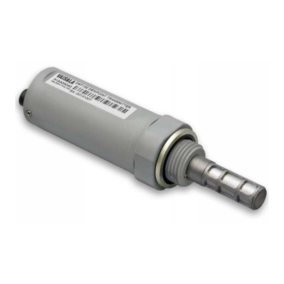
USER'S GUIDE____________________________________________________________________ 1101-047 ® Figure 1 Vaisala HUMICAP Dewpoint Transmitter DMT132 Basic Features and Options - Dewpoint measurement range -20 ... +50 °C (-4 ... +122 °F) T - Output in T or T atm (calculated quantity). - HUMICAP® polymer sensor . -
Page 13: Transmitter Structure
When the transmitter is delivered, the filter is protected by a yellow transport protection cap that keeps the sensor dry. The transport protection cap should be left on the transmitter during storage. Remove the transport protection cap before installing the transmitter. VAISALA _______________________________________________________________________ 11... -
Page 14: Led Indicator Plug (Optional)
LED Indicator Plug (Optional) The service port (connector II) of the DMT132 can be equipped with a LED indicator plug (Vaisala order code 230388). The red LED on the plug will light up when the measured dewpoint temperature is above the set limit. -
Page 15: Special Cover Set For Hmk15 (Optional)
Special Cover Set for HMK15 (Optional) To use the Vaisala Humidity Calibrator HMK15 with the DMT132 you need the special cover set (Vaisala order code 230914). The cover set includes one salt jar cover where one of the holes is specially designed for the DMT132, and rubber plugs for covering the unused holes. -
Page 16: Npt Adapter (Optional)
USER'S GUIDE____________________________________________________________________ NPT Adapter (Optional) The DMT132 can be connected to NPT 1/2" threaded mounting points using the optional NPT adapter (Vaisala order code 210662). 1101-061 Figure 5 DMT132 with NPT Adapter When the NPT adapter is used, the filter is partially covered by the NOTE adapter;... -
Page 17: Loop-Powered Display (Optional)
Loop-Powered Display (Optional) The DMT132 can be connected to a loop-powered external LED display (type Nokeval 301, Vaisala order code 226476). The display provides a reading of the output quantity. The display is powered by the 4 ... 20 mA current signal, so there is no need for an external power supply. -
Page 18: Connection Cables
USER'S GUIDE____________________________________________________________________ Connection Cables Vaisala supplies shielded cables with M8 female straight threaded connector. Available in four lengths: - 0.3 m (1.0 ft) - 3 m (9.8 ft) - 5 m (16.4 ft) - 10 m (32.8 ft) Also available are cables for service port and field check use:... -
Page 19: Sampling Accessories
DMT132 is compatible with various sampling accessories. For more information on performing sampling, and a description of the accessories, see section Sampling Accessories on page 17. For the order codes of the sampling accessories, refer to section Spare Parts and Accessories on page 69. VAISALA _______________________________________________________________________ 17... - Page 20 USER'S GUIDE____________________________________________________________________ This page intentionally left blank. 18 __________________________________________________________________ M211289EN-A...
-
Page 21: Chapter 3 Installation
Sampling from the process is easy by using Vaisala sampling cell options; see section Sampling Accessories on page 25. The DMT132 is light in weight, which means that it can be installed in a sample pipeline in the sampling cells without the need of any additional mechanical support. -
Page 22: Installing The Transmitter
USER'S GUIDE____________________________________________________________________ Installing the Transmitter After selecting a suitable measurement location, follow the procedure below to install the transmitter: Remove the yellow transport protection cap from the transmitter. 1101-062 Figure 9 Removing the Transport Protection Cap If you are using the optional NPT adapter, apply PTFE tape or suitable paste sealant to the outer thread of the adapter. -
Page 23: Figure 11 Tightening By Hand
Sufficient tightness is achieved by turning 20 degrees after the point achieved by hand. CAUTION Only tighten the transmitter from the 30 mm nut. Do NOT apply force to other points in the transmitter body. 1101-064 Figure 12 Tightening with the Plastic Wrench VAISALA _______________________________________________________________________ 21... -
Page 24: Figure 13 Connecting The Cable And Led Indicator Plug
USER'S GUIDE____________________________________________________________________ Connect the wires of the connection cable. When using cables provided with DMT132 refer to the wiring section on page 23. See the power supply requirements on page 24. 1101-066 Figure 13 Connecting the Cable and LED Indicator Plug Plug in the cable to connector I of the transmitter and tighten it. -
Page 25: Wiring
RS-485 D1+ Black 1101-082 Figure 14 Connectors I and II 1 = VDC+ 3 = GND 1 = VDC+ 4 = RS-485 D1+ RS-485 2 = RS-485 D0- 3 = GND 1101-068, 1101-069 Figure 15 Connector Pinout VAISALA _______________________________________________________________________ 23... -
Page 26: Power Supply Requirements
Make sure there is sufficient flow of gas to the sensor (for example, 1 l/min) to give a representative sample. You can use the Vaisala Humidity Calculator to simulate the effect of pressure change to dewpoint. The Humidity Calculator can be found at: www.vaisala.com/humiditycalculator... -
Page 27: Sampling Accessories
1/4" tubing. To fit 6 mm tubing to the connectors, an adapter such as Swagelok® Reducer SS-6M0-R-4 (not supplied by Vaisala) can be used. DMT242SC2 is the suitable choice in, for example, plastics drying systems, where the measurement is made by tapping off the dryer system and bringing a small air stream to the sensor. -
Page 28: Dsc74 Sampling Cell With Quick Connector And Leak Screw
USER'S GUIDE____________________________________________________________________ 0801-069 Figure 16 Sampling Cells DMT242SC2 (left) and DMT242SC (right) where Male pipe welded connector Swagelok 1/4" G1/2" G1/4" G3/8" DSC74 Sampling Cell with Quick Connector and Leak Screw The DSC74 has been designed especially for compressed air lines. The sampling cell contains an adjustable leak screw that allows keeping up the pipeline pressure at the sensor. -
Page 29: Dsc74B Two-Pressure Sampling Cell
Harmful gases can be recovered by connecting a collection system at the outlet (not available from Vaisala). In the basic operation of the DSC74B, the gas flows to the sensor from the front and the outlet is on the side. -
Page 30: Figure 18 Dsc74B
USER'S GUIDE____________________________________________________________________ atmospheric pressure, the inlet and outlet are reversed. Then the reducing parts supplied (G3/8" - G1/2" or G3/8" - G1/4") on the outlet side help to protect the sensor from ambient humidity coming in. DSC74B parts are: - Sampling cell, thread 3/8"G - Connection part with a needle valve and an integrated leak screw - Reducing Nipple (thread adapter), G3/8"... -
Page 31: Dsc74C Two-Pressure Sampling Cell With Coil
- Reducing Adapter (thread adapter), G3/8" - G1/4" - Diffusion coil (for measurements in atmospheric pressure) 0510-034 Figure 20 Default Assembly of DSC74C where Gas goes in. The coil can also be used here. Gas comes out Coil Valve VAISALA _______________________________________________________________________ 29... -
Page 32: Figure 21 Alternative Assembly Of Dsc74C (For Tight Spaces)
USER'S GUIDE____________________________________________________________________ 0403-113 Figure 21 Alternative Assembly of DSC74C (for Tight Spaces) where Gas comes out Coil Thread, max. size 7 mm Gas goes in Valve The thread size cannot exceed 7 mm. Use the provided adapter to avoid damage to the transmitter. 30 __________________________________________________________________ M211289EN-A... -
Page 33: Dm240Fa Duct Installation Flange
1102-001 Figure 22 DM240FA with DMT132 where Measured gas DMT132 transmitter DM240FA flange (thread G1/2" ISO) Recommended additional hole (plugged) for T field check reference measurement probe (for example, Vaisala DM70) VAISALA _______________________________________________________________________ 31... - Page 34 USER'S GUIDE____________________________________________________________________ This page intentionally left blank. 32 __________________________________________________________________ M211289EN-A...
-
Page 35: Chapter 4 Operation
Connecting to the Serial Interface The DMT132 can be connected to a PC using the RS-485 line on Port II. It is recommended that you use the USB service cable (Vaisala order code 219690) for the connection, since the cable also provides the operating power from the USB port. -
Page 36: Terminal Application Settings
There is no reason to uninstall the driver for normal use. However, if you wish to remove the driver files and all Vaisala USB cable devices, you can do so by uninstalling the entry for Vaisala USB Instrument Driver from the Add or Remove Programs ( Programs and Features in Windows Vista) in the Windows Control Panel. -
Page 37: Figure 23 Putty Terminal Application
Serial line to connect to field. Note: You can check which port the USB cable is using with the Vaisala USB Instrument Finder program that has been installed in the Windows Start menu. Check that the other serial settings are correct for your connection, and change if necessary. -
Page 38: List Of Serial Commands
HELP Display the command list View user adjustment parameters Set user adjustment parameters PASS Access advanced service commands. Requires passcode. Use when instructed by Vaisala personnel. PRES Set value for pressure compensation RHCAL Calibrate humidity measurement RESET Reset the transmitter... -
Page 39: Device Information And Status
The ? command outputs a listing of device information. ? <cr> Example: >? >Device Name : DMT132 Dewpoint transmitter Calibrated : "20110223" Calibration location: "VAISALA/HEL" Serial number : "G0831004" Batch number : "G0000007" Sensor model : "HUMICAP180R" Sensor serial number: "F312"... -
Page 40: Show Software Information
USER'S GUIDE____________________________________________________________________ Show Software Information SYSTEM <cr> Example: >system Device Name : DMT132 Dewpoint transmitter Copyright : Copyright (c) Vaisala Oyj 2011. All rights reserved. SW Name : DMT132 SW model : VAISALA SW version : 1.0.0.1214 > Configuring Analog Output... -
Page 41: Set Analog Output Error Notification
Saving settings...done > The error output value is displayed only when there are minor electrical NOTE faults such as a humidity sensor damage. When there is a severe device malfunction, the error output value is not necessarily shown. VAISALA _______________________________________________________________________ 39... -
Page 42: Configuring Measurement Parameters
USER'S GUIDE____________________________________________________________________ Configuring Measurement Parameters Set Pressure Value for Dewpoint Calculation The HUMICAP® 180R sensor in the DMT132 is not very pressure- dependent. However, to maximize the measurement accuracy, the pressure of the system must be known. The pressure compensation value has been set at the factory according to the order form. -
Page 43: Serial Line Output Commands
Possible errors and their causes are listed in Table 8 on page 65. ERRS <cr> Example (no errors active): >errs No errors > Example (Error E2 active): >errs Error: E2 Humidity sensor open circuit/not calibrated > VAISALA _______________________________________________________________________ 41... -
Page 44: Test Analog Output
Analog output value, range 0 ... 30 mA. The output shows the test value of the analog output as well as diagnostic information that may be useful to Vaisala Service if there is a problem with the analog outputs. Example (enabling analog output test mode with 20 mA output): >atest 20... -
Page 45: Calibration And Adjustment Commands
RH > 50%. Example (one-point calibration): >rhcal 11.278554 Ref1 ? 11.3 Press any key when ready Saving settings...done > Example (two-point calibration): >rhcal 11.278554 Ref1 ? 11.3 Press any key when ready 75.091213 Ref2 ? 75 Saving settings...done > VAISALA _______________________________________________________________________ 43... -
Page 46: Calibrate Temperature Measurement
USER'S GUIDE____________________________________________________________________ Calibrate Temperature Measurement Use the CT command to perform a one-point or two-point temperature (T) calibration. CT <cr> When performing a one-point calibration, you need to place the transmitter in a single temperature reference. Run the command and enter the exact temperature of the reference after the measurement has stabilized. -
Page 47: Adjust Capacitance Measurement
Example: one-point adjustment >crh 11.41200712 Ref1 ? 11.3 Press any key when ready > Example: two-point adjustment >crh 11.41200712 Ref1 ? 11.3 Press any key when ready 74.72910210 Ref2 ? 75 > VAISALA _______________________________________________________________________ 45... -
Page 48: View User Adjustment Parameters
USER'S GUIDE____________________________________________________________________ View User Adjustment Parameters Use the L command to view the current user adjustment parameters that are affected by the CRH , RHCAL , CT , and LI commands. This command is useful for checking the currently applied correction. L <cr>... -
Page 49: Other Commands
Reset Transmitter When the RESET command is given, the transmitter will restart as if it had just been powered on. All transmitter settings are retained. RESET <cr> Example: >reset DMT132 1.0.0 2011-02-03 Type "help" for command list > VAISALA _______________________________________________________________________ 47... -
Page 50: Restore Factory Settings
LI command. See page 46. NOTE If the HUMICAP® sensor has been changed at a Vaisala Service Center the factory calibration has been updated to match the new sensor, and it will not be affected by the FRESTORE command. -
Page 51: Chapter 5 Maintenance
Changing the Filter If the filter is contaminated, it should be replaced. New filters can be ordered from Vaisala (order code 230602). Be careful when changing the filter, since it is easy to break the sensors when the filter is removed. -
Page 52: Figure 24 Opening The Filter
Opening the Filter 1102-004 Figure 25 Filter Structure where Sealing ring (replace if damaged) Vaisala HUMICAP® 180R sensor and Pt1000 temperature sensor Spring washer Tube filter Replace the filter as follows: Turn the filter counterclockwise until it is loose. Pull the filter straight out carefully; do not damage the sensors, and do not lose the spring washer. -
Page 53: Changing The Sensor
Attach a new filter on the probe as instructed in section Changing the Filter on page 49.. Perform a two-point calibration and adjustment using the CRH command as instructed in section Capacitance Adjustment (CRH) on page 60. 1103-005 Figure 26 Removing the HUMICAP® 180R Sensor VAISALA _______________________________________________________________________ 51... -
Page 54: Calibration And Adjustment
For more information, see section Field Check Using DM70 on page 53. To have the transmitter calibrated and adjusted by Vaisala, contact a Vaisala Service Center or your local Vaisala representative. See section Technical Support on page 66. -
Page 55: Field Check Using Dm70
- You can also use a second DMT132 transmitter. - A connection cable between DMT132 and the MI70 indicator (Vaisala order code 219980). - A reference environment with a stable dewpoint and temperature in a suitable range for both devices. - Page 56 If the difference is more, the DMT132 is in need of adjustment. You can have the DMT132 adjusted by a Vaisala Service Center (see page 66), or adjust the transmitter yourself by following the procedure Humidity Calibration and Adjustment (RHCAL) on page...
-
Page 57: Humidity Calibration And Adjustment (Rhcal)
(RHCAL) The procedure below describes a humidity measurement calibration and adjustment using the serial line commands and the Vaisala Humidity Calibrator HMK15. You can use the procedure to do a one-point calibration (offset) or a two-point calibration (offset and gain). - Page 58 USER'S GUIDE____________________________________________________________________ Disconnect the cable from connector I of the DMT132 (if connected). Connect the USB cable to connector II on the DMT132, and to a USB port on your PC. Start a terminal application and set the service port connection settings ( 19200 8 N 1) .
- Page 59 The RHCAL command is now finished and both adjustments have been applied. Use the L command to verify that the new user adjustment parameters are in use: >l Use the SEND command to verify that the measurement is OK: >send Tdf= -9.33'C > VAISALA _______________________________________________________________________ 57...
-
Page 60: Temperature Calibration And Adjustment (Ct)
USER'S GUIDE____________________________________________________________________ Temperature Calibration and Adjustment (CT) The procedure below describes a temperature (T) measurement calibration and adjustment using serial line commands. You can use the procedure to do a one-point calibration (offset) or a two-point calibration (offset and gain). For two-point calibration, the second reference point must be at least 20 º... - Page 61 The CT command is now finished and both adjustments have been applied. Use the L command to verify that the new user adjustment parameters are in use: >l Use the SEND command to verify that the measurement is OK: >send Tdf= -1.25'C > VAISALA _______________________________________________________________________ 59...
-
Page 62: Capacitance Adjustment (Crh)
CRH command. See section Restore Factory Settings on page 48. The procedure below adjusts the capacitance measurement of the transmitter using the serial line commands and the Vaisala Humidity Calibrator HMK15. You can use the procedure to do a one-point adjustment (offset) or a two-point adjustment (offset and gain). - Page 63 - To apply the correction, press ENTER one last time to update the value, type 11 and press ENTER again (assuming you are using the HMK15 and the LiCl salt). - To exit the CRH command without adjusting the measurement, press the ESC key and exit this procedure. VAISALA _______________________________________________________________________ 61...
- Page 64 USER'S GUIDE____________________________________________________________________ If you only want to perform a one-point adjustment (offset correction), press the ESC key after entering the correction. The CRH command will exit, and you can move to step 16. 11.35423321 Ref1 ? 11 Press any key when ready >...
-
Page 65: Chapter 6 Troubleshooting
If you cannot solve the problem and return the transmitter to the normal state, please contact Vaisala technical support. See section Technical Support on page 66. If repair is needed, you can have the transmitter serviced by a Vaisala Service Center. See section Product Returns on page 66. VAISALA _______________________________________________________________________ 63... -
Page 66: Error State
USER'S GUIDE____________________________________________________________________ Error State If the voltage supplied to the DMT132 is too low for reliable operation, or there is some serious problem that prevents measurement, the DMT132 will enter an error state. The error state is indicated by the following: - Analog current output is set to the error level (default is 3.8 mA) - If the LED indicator plug option is installed, the LED is blinking. -
Page 67: Error Codes
This error may occurr when the (ATEST) analog output is in test mode. See page Test Analog Output on page Default settings not found Internal error RH reading too high Internal error RH reading too low Internal error Log corrupted Internal error VAISALA _______________________________________________________________________ 65... -
Page 68: Technical Support
USER'S GUIDE____________________________________________________________________ Technical Support For technical questions, contact the Vaisala technical support by e-mail at helpdesk@vaisala.com. Provide at least the following supporting information: - Name and model of the product in question - Serial number of the product - Name and location of the installation site - Name and contact information of a technically competent person who can provide further information on the problem. -
Page 69: Chapter 7 Technical Data
33 s (63 %) 85 s (90 %) Accuracy ±1 °C Accuracy ±2 °C Temperature of measured gas (°C) 1101-058 Figure 28 Accuracy Over Temperature Range When dewpoint is below 0 °C, the transmitter outputs frostpoint for T VAISALA _______________________________________________________________________ 67... -
Page 70: Calculated Variables
Connector 4-pin M8 (IEC 60947-5-2) LED indication available for defined dewpoint limit/error state indication RS485 serial line for service use General Sensor Vaisala HUMICAP®180R Recommended calibration interval 2 years Mechanical connection G 1/2" ISO Operating voltage 10 ..28 VDC max 100 Ω... -
Page 71: Output Cable Specifications
Sampling cell DMT242SC Sampling cell with 1/4" male Swagelok connectors DMT242SC2 Sampling cell with quick connector and leak screw DSC74 Two-pressure sampling cell DSC74B Two-pressure sampling cell with coil DSC74C Separate cooling/venting coil for sampling cells DMCOIL VAISALA _______________________________________________________________________ 69... -
Page 72: Dimensions In Mm
USER'S GUIDE____________________________________________________________________ Dimensions in mm 125.5 80.5 G1/2" ISO 228-1 AW 30 1101-048 Figure 29 DMT132 Dimensions 20.5 NPT 1/2" AW 27 1101-060 Figure 30 Dimensions with NPT Adapter and LED Plug 70 __________________________________________________________________ M211289EN-A... - Page 74 *M211289EN*...
Need help?
Do you have a question about the HUMICAP DMT132 and is the answer not in the manual?
Questions and answers