Table of Contents
Advertisement
NITESTAR OPERATION MANUAL
Copyright © 2004 Nu-Metrics. All rights reserved.
This document contains or refers to proprietary information that is
www.nu-metrics.com
protected by copyright or patents. Copying or other reproduction of
this document and associated software, for sale or distribution, is
prohibited without the prior written permission of Nu-Metrics.
Windows
is a trademark of the Microsoft
Corporation.
™
®
Vehicle-Installed Distance Measuring Instrument
INSTALLATION & OPERATION
518 University Drive
REFERENCE GUIDE
Uniontown, PA 15401 • USA
Phone: (724) 438-8750 • Fax: (724) 438-8769
Models NS-50 / NS-60
w w w . n u - m e t r i c s . c o m
Accurate Distance Measuring From Your Vehicle!
Nu-Metrics, Hi-Star and Highway Data Management (HDM) Software are trademarks of Nu-Metrics.
Copyright © 2004 Nu-Metrics. All Rights Reserved.
PRINTED IN THE U.S.A.
REV 10/6/2004
Advertisement
Table of Contents

Summary of Contents for NU-METRICS NITESTAR
- Page 1 . n u - m e t r i c s . c o m Accurate Distance Measuring From Your Vehicle! Nu-Metrics, Hi-Star and Highway Data Management (HDM) Software are trademarks of Nu-Metrics. Copyright © 2004 Nu-Metrics. All Rights Reserved.
-
Page 2: Table Of Contents
PDI Count Use ......25 Wiring The Nitestar ......4 EMERGENCY 9-1-1 PROGRAM . -
Page 3: Nitestar Ns-50 And Ns-60
– WARNING – get(s) attached to the u-joint or the drive shaft. Do not mount a Nitestar in any area that may block the driver's The transmission sensor transmits six pulses for each revolution view or cause other obstructions. -
Page 4: Wiring The Nitestar
STOPS or freezes the display, DMI is still counting inter- nally but the display value is stopped so you may write it WIRING THE NITESTAR - CAUTION! down. The words DISPLAY/HOLD will flash in the status Failure to connect the power and ground wires directly to the window when the instrument is in hold. - Page 5 Event # Distance Interval Speed <Return> number of 1000. This value should remain in the Nitestar until the 12345 proper calibration procedure is completed as outlined in this man- ual. If 1000 is not programmed in, manually type in “1000” and 12445 press the MARK/ENTER key.
-
Page 6: Disp/Hold
4. The display will show: The display should show the course length. 7. Make sure this value is saved by turning the Nitestar off. (Press the ON/OFF key). 8. If this is the first time you have calibrated a DMI, repeat the... -
Page 7: On/Off
CALIBRATION SUMMARY (AUTOMATIC) MEMORY The NITESTAR has 99 memory locations. Each location can store With the instrument in COUNT/HOLD: an event and a distance. For example, 99 intersecting street locations can be stored in memory with their corresponding dis- tances. These values are saved in the permanent memory so •... -
Page 8: Recalling Events From Memory
VIEW : Exits memory store. Now the NITESTAR is back to Depressing the MARK/ENTR key will store the code and the cur- standard operation mode. rent distance into memory. When you do this the MARK value will go up by one and the code will become 00 again. -
Page 9: Memory Store Summary
For example, a printout RUN/HOLD : Starts/stops NITESTAR counting would look as follows: VIEW : Exits memory store. Now the NITESTAR is back to stan- Event# Distance Delta Code dard operation. -
Page 10: Changing Memory Output Format
CHANGING MEMORY OUTPUT FORMAT After doing this your memory transfer would be: The code output by the NITESTAR can be either the number input Event# Distance Delta Code by the user as shown above or you have the option of automati- STA.M... -
Page 11: Survey Data Management Software
• Ability to utilize optional GPS sensor Acquisition/Reacquisition Performance: < 15 seconds Time to Cold Start < 120 seconds. Initially, the SDM software is used in conjunction with the Nitestar 60 Antenna: GPS passive DMI, which is interfacing with a laptop computer during a survey. -
Page 12: Ttl Pdi Wiring
STEP 1 : Press the following keys: 8PDI key, 3PD key (number CABLE FRONT VIEW of milliseconds), MARK/ENTR key. 1000 mill-secs = 1 sec. TO THE NITESTAR DMI TELEPHONE-TYPE FLAT CABLE (BLACK, 8 FT.) 1 2 3 4... -
Page 13: Setting The Type Of Pdi
SETTING THE TYPE OF PDI The device that uses the PDI signal sometimes has certain requirements for the signal. The NITESTAR can produce three types of PDI. Let us take for example a PDI set for every 10 feet and a duration of 1 millisecond. -
Page 14: Advanced Pdi Uses
…and your output would be: SET COUNT PRE-DISTANCE To have your PDI count to start at a value other than 0 depress the following sequence of keys: 8PDI key, 8PDI key again, (ENTER PREDISTANCE VALUE), MARK/ENTR key. The value will appear in the INTERVAL window. -
Page 15: Set Count Increment
At this time re-enter the value of unit measurement need- ed. Then press MARK/ENTER key. The NITESTAR has other specialized functions that are accessed by pressing the PRM key then a number key. These are functions SET COUNT INCREMENT... -
Page 16: Speed Trap (Prm 6)
7 : To EXIT the speed trap program press CLEAR. tion for information on the use of this operation. Some of the func- If you have the RS-232 option and a printer the NITESTAR will output a tions are described here. Others such as memory and baud rate count and speed each time the program calculates a new speed. - Page 17 JOB- Distance * width * thickness * cost = $ again to exit this calculation. --- The NITESTAR will remember your (amount in cost units i.e. $’s). inputs so you won’t have to input the constants such as lane width or Depress MARK/ENTR key after each entry, press MARK/ENTR again to cost each time.
-
Page 18: Area Calculation (Prm 10)
TSD software. TIME-SPEED-DELAY USE STEP 1 : Make sure your NITESTAR is version 3.0 or above, when you PRINTER USE turn it on make sure it shows 3.0 or greater in the interval window. (It... -
Page 19: Operation
& turn off the printer when not in use to preserve battery life. OPERATING THE PRINTER STEP 1 : Turn off printer power switch and Nitestar power switch. STEP 2 : Connect printer & Nitestar with interface cable. STEP 3 : Turn on power switches to the Nitestar & DPU-414. -
Page 20: Opening The Paper Holder
Always wear safety goggles and protective clothing. 3. Plug in the Nitestar and turn it on. It should begin its Self- Check, when completed (0) should be displayed in the Speed &... -
Page 21: Limited Warranty
Instrument is operational but does not count. to remedy any such defect or to furnish a new part in exchange If the Nitestar has power and is operational but does not count, for any part of any unit of its manufacture which under normal the trouble is most likely installation or sensor related. -
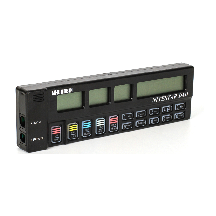
Page 22: Clear/Reset
What follows is the setup you have PREDIST key to do ONCE so Hyperterminal will work with your NS-60. Name UP/DOWN key the description "Nitestar" and give it an ATOMIC icon. Display Brightness key PRINT key Click OK to move to the next step. - Page 23 Finally pick Exit on Hyperterminal and then you will see you now Pick the Settings tab and you will get: have a connection ICON for the Nitestar. Pick that to start the program the next time.
-
Page 24: Specifications
USING HYPERTERMINAL SPECIFICATIONS NITESTAR NS-50/60 Start Hyperterminal by launching your new Nitestar icon. POWER: 9 to 16 VDC, negative ground. You can now issue the CAPTURE TEXT command to your NS-60. OPERATING TEMPERATURE: 0 degrees C to +70 degrees C. -
Page 25: Nitestar Return Form
SERVICE OF YOUR EQUIPMENT If your equipment should ever need servicing, you must contact the Nu-Metrics’ Service Department to acquire an RMA number to be included with your shipment. Please provide a description of the problem, your name, telephone number, complete return address and desired method of shipment with the product(s) you are return- ing. - Page 26 Addendum to Nitestar Wiring on Page 4 PROXIMITY SENSOR WIRING DIAGRAM TO THE NITESTAR DMI TELEPHONE-TYPE FLAT CABLE (BLACK, 8 FT.) MOUNT TERMINAL BLOCK TO FENDER WELL USING #6-32 METAL TAP SCREWS 250 volt 1 amp fuse + RED WIRE DIRECTLY TO...
Need help?
Do you have a question about the NITESTAR and is the answer not in the manual?
Questions and answers