
Subscribe to Our Youtube Channel
Summary of Contents for Campbell AVW200 series
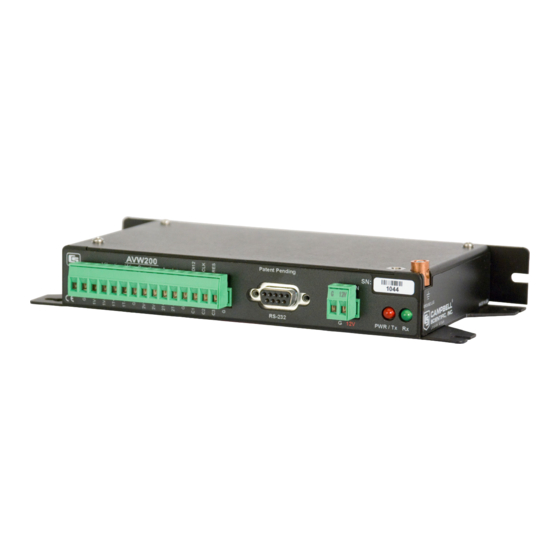
- Page 1 AVW200-series 2-Channel Vibrating Wire Spectrum Analyzer Modules Revision: 2/12 C o p y r i g h t © 2 0 0 8 - 2 0 1 2 C a m p b e l l S c i e n t i f i c , I n c .
- Page 3 Campbell pricelist or product manual. Products not manufactured, but that are re-sold by Campbell, are warranted only to the limits extended by the original manufacturer. Batteries, fine-wire thermocouples, desiccant, and other consumables have no warranty.
- Page 4 SCIENTIFIC, INC., phone (435) 227-2342. After an applications engineer determines the nature of the problem, an RMA number will be issued. Please write this number clearly on the outside of the shipping container. Campbell Scientific's shipping address is: CAMPBELL SCIENTIFIC, INC.
-
Page 5: Table Of Contents
AVW200-series Table of Contents PDF viewers: These page numbers refer to the printed version of this document. Use the PDF reader bookmarks tab for links to specific sections. 1. Overview...............1 1.1 Design Features ..................1 1.2 Specifications....................3 1.3 Communication..................3 1.3.1 Datalogger..................3 1.3.1.1 PakBus Protocol/Direct RS-232 Connection ......4 1.3.1.2 PakBus Protocol/Wireless Connection........4 1.3.1.3 PakBus Protocol/MD485 Communication ......4... - Page 6 AVW200-series Table of Contents 5.3 Data Monitor..................30 5.4 Send OS ....................32 5.5 Troubleshoot ..................33 5.6 Settings Editor..................36 5.7 Terminal....................36 6. Programming..............37 6.1 AVW200 Instruction................37 6.1.1 Pipeline Mode ................41 6.1.2 Sequential Mode................41 6.2 SDI-12 Measurements ................42 6.2.1 SDI12 Recorder() Instruction............
- Page 7 AVW200-series Table of Contents C.3 Surge Protectors ...................C-5 C.3.1 Electrostatic Issues ..............C-5 C.3.2 Antenna Surge Protector Kit ............C-6 C.4 Part 15 FCC Compliance Warning ............C-6 D. The Public Table............D-1 D.1 Forced Measurement Program............D-4 E. Status Table ............. E-1 F.
- Page 8 AVW200-series Table of Contents 4.5.2-2. Multiplexer to Datalogger Power/Control Hookup (multiplexer controlled by datalogger) ............24 5.1-1. Opening Page in DevConfig.............. 26 5.2.1-1. Deployment Communications Editor in DevConfig....... 27 5.2.2-1. Deployment/Measurement Tab in DevConfig........ 29 5.3-1. Data Display/Public Table in DevConfig .......... 30 5.3-2.
-
Page 9: Overview
AVW200-series 2-Channel Vibrating Wire Spectrum Analyzer Modules The AVW200 series consist of a base model (AVW200) and three wireless models (AVW206, AVW211, AVW216). The wireless models combine the AVW200 with a spread spectrum radio. The different model numbers of the wireless versions are for different spread spectrum frequency ranges. - Page 10 AVW200-series 2-Channel Vibrating Wire Spectrum Analyzer Modules The eliminated parameters are: • Number of steps • Number of cycles • Time of Swept Frequency These parameters are now part of the AVW200 internal operating system and require no user input. The user only needs to input the lower frequency range, upper frequency range, and excitation voltage of the sensor.
-
Page 11: Specifications
AVW200-series 2-Channel Vibrating Wire Spectrum Analyzer Modules 1.2 Specifications 1.3 Communication 1.3.1 Datalogger The AVW200 module is designed to work with and complement Campbell Scientific dataloggers, as well as data acquisition products from other manufacturers. -
Page 12: Pakbus Protocol/Direct Rs-232 Connection
1.3.1.4 SDI-12 Communication Mode SDI-12 is the only option available for our CR5000, CR10X, and CR23X dataloggers and non-Campbell Scientific dataloggers. Our CRBasic dataloggers use the SDI12Recorder instruction and Edlog dataloggers (i.e., CR10X, CR23X) use Instruction 105. The SDI12Recorder instruction should only be run in the sequential mode. -
Page 13: Computer
To use DevConfig, the AVW200 must be connected to a PC and a power source. DevConfig is bundled in Campbell Scientific’s datalogger support software and can also be acquired, at no cost, from Campbell Scientific’s website. - Page 14 AVW200-series 2-Channel Vibrating Wire Spectrum Analyzer Modules AM16/32B AVW200 CR3000 COM1 (C1/C2) CR1000 COM2 (C3/C4) COM3 (C5/C6) COM4 (C7/C8) 128 – Vibrating Wire Sensors in 4x16 configuration 256 – Vibrating Wire Sensors in 2x32 configuration FIGURE 1.4-1. Network of AVW200s and AM16/32Bs (using a direct RS-232 connection) AVW206 AM16/32B CR3000...
-
Page 15: Measurements
AVW200-series 2-Channel Vibrating Wire Spectrum Analyzer Modules AM16/32B CR10X AVW200 CR5000 CR23X CR800, CR850 CR1000 CR3000 SDI-12 Datalogger MUST Control Multiplexers in SDI-12 Mode FIGURE 1.4-3. Network of AVW200 Interfaces (SDI-12) 2. Measurements 2.1 Vibrating Wire The spectral approach implemented by the AVW200 offers significantly improved noise immunity when compared to older period-averaging techniques implemented by other vibrating-wire interfaces (AVW1, AVW4, and AVW100). -
Page 16: Cutaway Of Vibrating Wire Sensor
AVW200-series 2-Channel Vibrating Wire Spectrum Analyzer Modules Vibrating Plucking/ Diaphragm Wire Pickup Coil FIGURE 2.1-1. Cutaway of Vibrating Wire Sensor There are three user-determined inputs to the AVW200 measurement process and five outputs from the measurement process. The input parameters control the excitation frequency range (BeginFreq and EndFreq) and the excitation amplitude (ExVolt);... -
Page 17: Avw200 Measurement Outputs
-555,555 is returned for the frequency measurement. This indicates to the user that there is a hardware issue on the device which requires a factory examination and/or repair. Contact Campbell Scientific for instructions when this value is given as the Resonant Frequency reading. -
Page 18: Temperature
AVW200-series 2-Channel Vibrating Wire Spectrum Analyzer Modules Response Noise Amplitude Amplitude Resonant Frequency Noise Frequency Ending Amplitude Beginning Amplitude FIGURE 2.1-2. DevConfig plots showing the AVW200 measurement approach. Please note that the use of the special FFT algorithm to achieve better noise immunity does require time for computation, which limits the maximum vibrating wire measurement rate to 2 seconds per sensor. -
Page 19: Quick Start Guides
AVW200-series 2-Channel Vibrating Wire Spectrum Analyzer Modules Read more! You can find an example program that converts resistance to temperature in Section 7.1.2 and detailed information about the thermistors in Appendix B. 3. Quick Start Guides The AVW200 can be used in many types of systems—from simple to complex. The following quick start guides provide steps used to set up a system for some example configurations. -
Page 20: Wireless Connection
AVW200-series 2-Channel Vibrating Wire Spectrum Analyzer Modules 4. Create a CRBasic program that includes an AVW200() instruction for each of the sensors. NOTE Check the manufacturer’s specification for the sensors frequency and excitation range before picking the begin/end frequencies and excitation voltage. For example, the following AVW200() instructions can be used to measure two sensors: AVW200(Result,Com1,200,200,Dst(1,1),1,1,1,1000,3500,2,_60HZ,1,0) - Page 21 AVW200-series 2-Channel Vibrating Wire Spectrum Analyzer Modules 2. Attach the vibrating wire sensor(s) to the AVW206 as shown in Figure 4.1-1. 3. Connect an antenna (or antenna cable with Yagi or omnidirectional antenna attached) to the Antenna Connector on the side of the AVW206. Read more! Description of our antenna options is provided in Appendix C.
-
Page 22: Multiplexers Controlled By Avw200
AVW200-series 2-Channel Vibrating Wire Spectrum Analyzer Modules 3.2 Multiplexers Controlled by AVW200 3.2.1 Direct RS-232 Connection Sensors Multiplexer AVW200 Datalogger Power Sensors Multiplexer Supply Cable that Comes with Sensor CABLE4CBL-L Four Conductor Cable 17855 Pigtailed Cable or 18663 Null Modem Cable 19246 Power Cable For this example configuration, vibrating wire sensors are attached to multiplexers, which are controlled by the AVW200. -
Page 23: Wireless Connection
AVW200-series 2-Channel Vibrating Wire Spectrum Analyzer Modules NOTE Check the manufacturer’s specification for the sensors frequency and excitation range before picking the begin/end frequencies and excitation voltage. For example, the following AVW200() instructions can be used to control two multiplexers: AVW200(Data1(),Com1,200,200,mux1(1,1),1,1,16,450,3000,2,_60HZ,1,0) AVW200(Data2(),Com1,200,200,mux2(1,1),2,1,16,450,3000,2,_60HZ,1,0) Where,... - Page 24 AVW200-series 2-Channel Vibrating Wire Spectrum Analyzer Modules At the AVW206 site, do the following steps: 1. Use DevConfig to configure the AVW206 for RF communications (Sections 5.1 and 5.2.1). 2. If you are not using the default multiplexer, go to the Deployment/Measurement tab in DevConfig and select the multiplexer you are using (Section 5.1 and 5.2.1).
-
Page 25: Multiplexers Controlled By Datalogger
(1) When using SDI-12, multiplexers have to be controlled by NOTES the datalogger. (2) SDI-12 is the only option available for our CR10X, CR23X, and CR5000 dataloggers. (3) SDI-12 is the only option available for non-Campbell Scientific dataloggers. -
Page 26: Connections
AVW200-series 2-Channel Vibrating Wire Spectrum Analyzer Modules The following steps are used: 1. Access DevConfig to configure the AVW200 for SDI-12 communications. Go to the Deployment/Measurement tab in DevConfig and enter the SDI-12 Address, multiplexer type, begin frequency, end frequency, and excitation (see Section 5.1 and 5.2.2). -
Page 27: Power And Ground
AVW200-series 2-Channel Vibrating Wire Spectrum Analyzer Modules AVW200 FIGURE 4.1-1. Wiring for Sensor Connections 4.2 Power and Ground Each AVW200 has a ground lug for connection to earth ground and a green connector for attachment to a power source (see Figure 4.2-1). NOTE Only connect the AVW200 ground lug to earth ground when the AVW200 is not directly connected to the datalogger. -
Page 28: Datalogger Wiring (Direct Connection)
AVW200-series 2-Channel Vibrating Wire Spectrum Analyzer Modules Connects to earth ground via an 8 AWG wire when not directly connected to a datalogger Connects to a power source via 19246 power cable Indicates AVW200 is connected to a power source FIGURE 4.2-1. -
Page 29: Wireless Connections (Avw206, Avw211, Avw216)
AVW200-series 2-Channel Vibrating Wire Spectrum Analyzer Modules TABLE 4.3-2. 17855 or SC110’s DTE Cable Wiring Wire Color of 17855 or SC110’s DTE Cable CR800, CR850 CR1000, CR3000 Brown C1 or C3 C1, C3, C5, or C7 White C2 or C4 C2, C4, C6, or C8 Yellow 4.4 Wireless Connections (AVW206, AVW211, AVW216) -
Page 30: Multiplexer Wiring
AVW200-series 2-Channel Vibrating Wire Spectrum Analyzer Modules Wireless communication requires the appropriate spread spectrum radio to be connected to the datalogger (see Table 4.4-1). DevConfig is used to configure the AVW206, AVW211, or AVW216 for RF communications (Sections 5.1 and 5.2.1). TABLE 4.4-1. -
Page 31: Datalogger Controlling The Multiplexer
AVW200-series 2-Channel Vibrating Wire Spectrum Analyzer Modules FIGURE 4.5.1-1. Example AM16/32-series to AVW200 Hookup (multiplexers controlled by AVW200) 4.5.2 Datalogger Controlling the Multiplexer When using SDI-12, the datalogger must control the multiplexer. Use the CABLE4CBL-L cable to connect the AVW200 to the multiplexer if the vibrating wire sensors contain a thermistor (see Figure 4.5.2-1). -
Page 32: Am16/32B To Avw200 Hookup (Am16/32Bs Controlled By Datalogger And Using Sdi-12)
AVW200-series 2-Channel Vibrating Wire Spectrum Analyzer Modules AVW200 FIGURE 4.5.2-1. AM16/32B to AVW200 Hookup (AM16/32Bs controlled by datalogger and using SDI-12) A CABLE4CBL-L cable is used to connect the multiplexer to the datalogger (see Figure 4.5.2-2). CR10X, CR800, CR3000, CR23X, CR850 CR1000 CR5000... -
Page 33: Device Configuration (Devconfig) Utility
12 V lead. 2. Connect the AVW200 to a COM port on your computer using the 10873 RS-232 cable (shipped with the AVW200). 3. Open DevConfig. 4. Under Device Type, click AVW200 Series (see Figure 5.1-1). -
Page 34: Deployment Tab
AVW200-series 2-Channel Vibrating Wire Spectrum Analyzer Modules FIGURE 5.1-1. Opening Page in DevConfig 5. Select the Serial Port matching the COM port on your computer in which the AVW200 is connected. 6. Press the Connect button. The device may take up to 60 seconds to respond to DevConfig, and for the current settings to be loaded into the Settings Editor. -
Page 35: Deployment Communications Editor In Devconfig
AVW200-series 2-Channel Vibrating Wire Spectrum Analyzer Modules FIGURE 5.2.1-1. Deployment Communications Editor in DevConfig NOTE Certain AVW206 settings must match the RF401 settings for communications between the interface and radio to be successful. Description of the Communication Settings follows: Protocol—choose "PakBus" for the “Protocol” setting. Please note that the “Protocol”... -
Page 36: Avw206 Power Modes And The Recommended Corresponding Rf401 Power Modes
AVW200-series 2-Channel Vibrating Wire Spectrum Analyzer Modules Net Address—enter the radio network address that matches all of the RF401 radios and other AVW206 in the network. Valid entries are 0-3 Power Mode—If not using a radio, select “Radio Off” for the Power Mode. Otherwise, select a power mode that works with the RF401’s power mode (see Table 5.2.1-1). -
Page 37: Measurement
AVW200-series 2-Channel Vibrating Wire Spectrum Analyzer Modules 5.2.2 Measurement The Deployment/Measurement Tab is used to configure the SDI-12 Address, multiplexer type, begin frequency, end frequency, and excitation (see Figure 5.2.2-1). FIGURE 5.2.2-1. Deployment/Measurement Tab in DevConfig The Begin Frequency, End Frequency, and excitation parameters NOTE in DevConfig are only used for the RS-232 (terminal commands) and SDI-12 communication modes. -
Page 38: Data Monitor
AVW200-series 2-Channel Vibrating Wire Spectrum Analyzer Modules Multiplexer Type—choose the appropriate multiplexer. The default multiplexer type is the AM16/32B. Begin Frequency—if using RS-232 (terminal commands) or SDI-12, enter the sensor manufacturer’s recommendation for the begin frequency. End Frequency—if using RS-232 (terminal commands) or SDI-12, enter the sensor manufacturer’s recommendation for the end frequency. -
Page 39: Data Display/Status Table In Devconfig
AVW200-series 2-Channel Vibrating Wire Spectrum Analyzer Modules Read more! Appendix D lists the fields in the public table and provides a brief description of each. The status table contains system operating status information accessible (see Figure 5.3-2). Note: DevConfig polls the status table at regular intervals, and then updates the status information. -
Page 40: Send Os
AVW200-series 2-Channel Vibrating Wire Spectrum Analyzer Modules 5.4 Send OS For most applications, Campbell Scientific does not anticipate that it will be necessary to download a new operating system to the AVW200. However, if a new operating system (OS) is required, in order to send a new OS to the AVW200 you will need Device Configurator (DevConfig) 1.10 or greater. -
Page 41: Troubleshoot
AVW200-series 2-Channel Vibrating Wire Spectrum Analyzer Modules 5.5 Troubleshoot The Troubleshoot tool in DevConfig can be used to evaluate the frequency spectrum of a sensor and to determine the most appropriate beginning and ending frequencies for a sensor. To access the Troubleshoot Tool, use the steps listed below: 1. -
Page 42: Options Tab Of The Troubleshoot Tool
AVW200-series 2-Channel Vibrating Wire Spectrum Analyzer Modules FIGURE 5.5-2. Options Tab of the Troubleshoot Tool 4. Select the AVW200 channel either 1 or 2 and the multiplexer channel that the sensor is attached. If not using a multiplexer, then set the multiplexer channel to one. -
Page 43: Graphs For Evaluating Spectral Analysis Of A Sensor
AVW200-series 2-Channel Vibrating Wire Spectrum Analyzer Modules Response Noise Amplitude Amplitude Resonant Frequency Noise Frequency Ending Amplitude Beginning Amplitude FIGURE 5.5-3. Graphs for Evaluating Spectral Analysis of a Sensor NOTE Check the manufacturer’s specification for the sensors frequency and excitation range before picking the begin/end frequencies and excitation voltage. -
Page 44: Settings Editor
AVW200-series 2-Channel Vibrating Wire Spectrum Analyzer Modules 5.6 Settings Editor The Settings Editor in DevConfig can also be used to enter the Deployment parameters (see Figure 5.2-1). Refer to Sections 5.2 and Sections 5.3 for a description of the setting parameters. 5.7 Terminal You can monitor the AVW200 with terminal commands via the terminal emulator in DevConfig or LoggerNet. -
Page 45: Programming
AVW200-series 2-Channel Vibrating Wire Spectrum Analyzer Modules When using the “Mcmm” terminal command, no other CAUTION method of measurement should be used or multiplexing will get out of sequence and measurement errors will result. Read more! Appendix D. lists the fields in the public table and provides a brief description of each. - Page 46 AVW200-series 2-Channel Vibrating Wire Spectrum Analyzer Modules the AVW200. If more than one AVW200 is used and the instructions are ran in a sequential mode, a different result variable should be specified for each AVW200 (see 6.1.2). The result codes are as follows: Code Description Communication successful.
- Page 47 AVW200-series 2-Channel Vibrating Wire Spectrum Analyzer Modules multi-dimensioned array of 5 or 6 if multiple sensors are being measured using a multiplexer. The first dimension is set equal to the number of sensors being measured and the second dimension is set equal to the number of values returned for each sensor (5 or 6).
- Page 48 AVW200-series 2-Channel Vibrating Wire Spectrum Analyzer Modules BeginFreq The BeginFreq parameter is the starting frequency to use for the vibrating wire measurement. The minimum value that can be entered is 100. Refer to the specifications of the vibrating wire sensor for recommended BeginFreq values. EndFreq The EndFreq parameter is the ending frequency to use for the vibrating wire measurement.
-
Page 49: Pipeline Mode
AVW200-series 2-Channel Vibrating Wire Spectrum Analyzer Modules 6.1.1 Pipeline Mode When the CRBasic program first starts running, the information specified in the AVW200( ) instruction is sent to the attached AVW200 interface module via the communication port and PakBus address specified in the instruction. Along with the instruction's parameter information, the datalogger also sends its clock information. -
Page 50: Measurements
AVW200-series 2-Channel Vibrating Wire Spectrum Analyzer Modules different result variables for each AVW200( ) instruction, this situation can be detected. Therefore, the result variable for the first instruction would be zero (indicating successful communication) and the result variable for the second instruction would increment (indicating a failed communication). -
Page 51: Sdi-12 Command Codes
1) Chan1 Frequency (Measures AVW200 Channel 1; either 2) Chan1 Signal Amplitude mV this command or the following command is used for non-Campbell Scientific 3) Chan1 Signal-to-Noise Ratio dataloggers) 4) Chan1 Noise Frequency 5) Chan1 Decay Ratio 6) Chan1 Therm Resistance... -
Page 52: Extended Sdi-12 Commands
1. The SDI-12 address of the device (1 character) 2. The SDI-12 implementation version (2 characters, "13" is interpreted as 1.3) 3. The Vendor ID "Campbell" (8 Characters) 4. The Sensor Model "AVW2xx" (6 characters) 5. Sensor Version "000" (3 characters) 6. -
Page 53: Example Programs
AVW200-series 2-Channel Vibrating Wire Spectrum Analyzer Modules 7. Example Programs This section includes several program examples for our CR1000 datalogger. Although the examples are for the CR1000, programming for the CR800 and CR3000 is similar. Appendix G. has a programming example for the retired CR10X. -
Page 54: Wireless/One Sensor/Resistance Converted To Temperature
AVW200-series 2-Channel Vibrating Wire Spectrum Analyzer Modules CallTable avw200 CallTable avwcard NextScan EndProg 7.1.2 Wireless/One Sensor/Resistance Converted to Temperature 'This is an example of a program used by a CR1000 and AVW206 to one Geokon 4450 VW 'displacement sensor. The sensor provides a frequency, which is converted to displacement, and 'resistance, which is converted to temperature. -
Page 55: Avw200() Instruction Controlling Two Multiplexers
AVW200-series 2-Channel Vibrating Wire Spectrum Analyzer Modules 'Calculate displacement (inches) from Digits and calibration polynomial PSI=2.49866e-10*Digits^2 + 8.716e-5*Digits + -.2 NextScan EndProg 7.2 AVW200() Instruction Controlling Two Multiplexers Table 7.2-1 shows wiring used for this example. This program measures 16 sensors on each multiplexer. -
Page 56: Avw200( ) Instruction Running In The Pipeline Mode
AVW200-series 2-Channel Vibrating Wire Spectrum Analyzer Modules 7.3 AVW200( ) Instruction Running in the Pipeline Mode The following program is an example of how to run the AVW200 with a CR1000 using multiple AVW200( ) instructions in the pipeline mode of operation. -
Page 57: Avw200( ) Instruction Running In The Sequential Mode
AVW200-series 2-Channel Vibrating Wire Spectrum Analyzer Modules ' Example Program running in the PipeLine mode ' The clock and reset lines of both muxes are connected to the clk and rst ‘lines of the AVW200. PipeLineMode Public PTemp, batt_volt Public Result, AVWDst(32,6) Const Chan1 = 1 ' AVW200 channel 1 Const Chan2 = 2... -
Page 58: Avw200 Controlling Two Multiplexers In Sequential Mode
AVW200-series 2-Channel Vibrating Wire Spectrum Analyzer Modules Table 7.4-1 shows the wiring used for both Sequential Mode examples. TABLE 7.4-1. Wiring for Sequential Mode Examples Datalogger Port for Cable Needed to AVW200 Port or Cable Attachment connect to AVW200 Model COM1 (control port pairs 17855 Cable (pigtail to RS-232... -
Page 59: Example
AVW200-series 2-Channel Vibrating Wire Spectrum Analyzer Modules Const Chan1 = 1 ' AVW200 channel 1 Const Chan2 = 2 ' AVW200 channel 2 Const MuxChan = 1 ' Starting Mux Channel Const Reps = 1 ' Number of Reps Const BFreq = 450 ' Begin Frequency Const EFreq = 6000 ' End Frequency... -
Page 60: Sdi-12 Command Codes
AVW200-series 2-Channel Vibrating Wire Spectrum Analyzer Modules very next measurement will use the bbbb,eeee and vvvv values specified in the extended command. The second and remaining measurements will revert back to the settings specified via DevConfig. An example of an extended command is: 0XVW450,5000,1! This command will configure the next measurement with Begin Freq=450, End Freq = 5000 and 5Volt excitation. - Page 61 AVW200-series 2-Channel Vibrating Wire Spectrum Analyzer Modules ' Example Program running SDI12 commands with the Datalogger controlling ' 2 mux's. For this program, the AVW SDI-12 port is connected to DL C1. ' The reset line of both muxes is connected to datalogger C3. Mux1 clock line ' is connected to DL C4 and Mux2clock line is connected to DL C5.
-
Page 62: Troubleshooting Communication Problems
AVW200-series 2-Channel Vibrating Wire Spectrum Analyzer Modules 8. Troubleshooting Communication Problems 8.1 Unable to Communicate with DevConfig or Terminal Emulator If you are unable to communicate with DevConfig or the Terminal Emulator, verify that: (1) The AVW200 is powered. The red LED at the front of the AVW200 will remain lit for 15 seconds on initial power up and then blink intermittently. - Page 63 AVW200-series 2-Channel Vibrating Wire Spectrum Analyzer Modules Power supply must be able to sustain at least 9.6 V (datalogger minimum) even during 75 mA transmitter bursts lasting only a few milliseconds. Lightning damage to RF401 or AVW206 Swap in a known good RF401 or AVW206 with the same settings and see if this cures the problem.
- Page 64 AVW200-series 2-Channel Vibrating Wire Spectrum Analyzer Modules Change to a higher gain antenna Change polarization (element orientation) of all antennas in your network (yagi or collinear) from vertical to horizontal or vice versa. Interference from 900 MHz transmitter There are some measures you can take to reduce interference from neighboring 900 MHz transmitters: Move base station as far as possible from offending transmitter antenna.
-
Page 65: Conversion From Hertz
Appendix A. Conversion from Hertz The calibration report provided with each vibrating wire sensor contains the information required to convert Hertz, the frequency value output by the AVW200, to the appropriate units (e.g., displacement pressure). These steps convert Hertz to the appropriate unit (e.g., displacement, pressure): 1. -
Page 66: A.1-1. Geokon Calibration Report
Appendix A. Conversion from Hertz FIGURE A.1-1. Geokon Calibration Report of a Sensor without a Thermistor... -
Page 67: Thermistor Information
Appendix B. Thermistor Information B.1 Converting Resistance to Temperature The AVW200 outputs a resistance value for sensors that contain a thermistor. Temperature is calculated by applying the resistance to a known equation (e.g., Steinhart-Hart equation) which converts resistance to temperature. The Steinhart-Hart equation for converting resistance to degree Celsius is as follows: Temperature = 1/(A + B*LN(resistance) + C*(LN(resistance))^3) - 273.15... -
Page 68: B.2-1. Temperature Measurement Error At Three Temperatures As A Function Of Lead Length
Appendix B. Thermistor Information 4. Precision of the bridge resistors 5. Accuracy of the datalogger's voltage measurement 6. Temperature coefficient of the bridge resistors Errors three through six can probably be ignored. The wire resistance is primarily an offset error and its affect can be removed by the initial calibration. Errors caused by the change in wire resistance due to temperature and thermistor interchangeability are not removed by the initial calibration. -
Page 69: B.2-2. Temperature Measurement Error On A 1000 Foot Lead
Appendix B. Thermistor Information FIGURE B.2-2. Temperature Measurement Error on a 1000 foot Lead. Wire is 22 AWG with 16 ohms per 1000 feet. FIGURE B.2-3. Temperature Measurement Error on a 3000 foot Lead. Wire is 22 AWG with 16 ohms per 1000 feet. -
Page 70: B.2-4. Temperature Measurement Error On A 5000 Foot Lead
Appendix B. Thermistor Information FIGURE B.2-4. Temperature Measurement Error on a 5000 foot Lead. Wire is 22 AWG with 16 ohms per 1000 feet. -
Page 71: Antennas, Antenna Cables, And Surge Protectors For The Avw206, Avw211, And Avw216
Appendix C. Antennas, Antenna Cables, and Surge Protectors for the AVW206, AVW211, and AVW216 C.1 Antennas Several antennas are offered to satisfy the needs for various base station and remote station requirements. These antennas have been tested at an authorized FCC open-field test site and are certified to be in compliance with FCC emissions limits. - Page 72 Appendix C. Antennas, Antenna Cables, and Surge Protectors for the AVW206, AVW211, and AVW216 16005 0 dBd ANTENNA, 2.4 GHz, OMNI ½ WAVE WHIP, RPSMA RT ANGLE, LINX ANT-2.4-CW-RCT-RP, 4.5 inches long. 16755 13 dBd ANTENNA, 2.4 GHz, ENCLOSED YAGI, allows vertical or horizontal polarization, MAXRAD WISP24015PTNF, boom length 17 inches, diameter 3 inches, W/ END MOUNT to fit 1 to 2 in.
- Page 73 Appendix C. Antennas, Antenna Cables, and Surge Protectors for the AVW206, AVW211, and AVW216 ITEM # 14201 900 MHZ YAGI 9 dBd w/MOUNTS ITEM #14205 900 MHz YAGI 6 dBd w/MOUNTS ITEM # 14221 900 MHZ OMNI COLLINEAR 3 dBd w/MOUNTS...
-
Page 74: C.1-1. Some Fcc Approved Antennas
Appendix C. Antennas, Antenna Cables, and Surge Protectors for the AVW206, AVW211, and AVW216 ITEM #15970 900 MHZ Indoor OMNI 1 dBd Window/Wall Mounted ITEM #16005 2.4 GHz OMNI HALF WAVE WHIP 0 dBd ITEM #16755 2.4 GHz ENCLOSED YAGI, 13 dBd w/MOUNTS FIGURE C.1-1. -
Page 75: Antenna Cables
Appendix C. Antennas, Antenna Cables, and Surge Protectors for the AVW206, AVW211, and AVW216 FIGURE C.1-2. Example COAX RPSMA-L Cable for Yagi or Omni Colinear FIGURE C.1-3. Antenna Surge Protector C.2 Antenna Cables The 14201, 14203, 14205, 14221, and 16755 antennas require an antenna cable;... -
Page 76: Antenna Surge Protector Kit
C.4 Part 15 FCC Compliance Warning Changes or modifications to the AVW206, AVW211, or AVW216 not expressly approved by Campbell Scientific, Inc. could void the user’s authority to operate this product. Note: This equipment has been tested and found to comply with the limits for a Class B digital device, pursuant to part 15 of the FCC Rules. - Page 77 Appendix C. Antennas, Antenna Cables, and Surge Protectors for the AVW206, AVW211, and AVW216 This device complies with part 15 of the FCC Rules. Operation is subject to the following two conditions: 1) This device may not cause harmful interference, and 2) This device must accept any interference received, including interference that may cause undesired operation.
- Page 78 Appendix C. Antennas, Antenna Cables, and Surge Protectors for the AVW206, AVW211, and AVW216...
-
Page 79: The Public Table
Appendix D. The Public Table The public table of the AVW200 displays the current sensor measurement values as well as the current settings (see Table D-1). When the DeviceConfig runs the troubleshooter, it forces a measurement by writing to the Timeseries() array in the Public table. When the Timeseries(1)..Timeseries(4) elements are written with the proper values a measurement is performed and the files Timeseries.bin and Spectrum.bin are created or over-written if previous measurements have been forced. - Page 80 Appendix D. The Public Table Values and Control Parameters for SDI-12 Communications SDI12val(1) Frequency value obtained by SDI Recorder Instruction, if used; unchanged if not using SDI-12. SDI12val(2) Amplitude value obtained by SDI Recorder Instruction, if used; unchanged if not using SDI-12. SDI12val(3) Signal to noise ratio obtained by SDI Recorder Instruction, if used;...
- Page 81 Appendix D. The Public Table Control Parameters When Troubleshooter is Running TimeSeries(1) Writing this variable will force a Vibrating Wire measurement and create the TimeSeries.bin and spectrum.bin files. Example: 101 = measures AVW200 chan1 and Mux chan1 102 = measures AVW200 chan1 and Mux chan2 ..
-
Page 82: Forced Measurement Program
Appendix D. The Public Table D.1 Forced Measurement Program SequentialMode Public UsrForcedMsmnt Public SVResult(2), GVResult(2), TimeSeries(11) Dim TS_done BeginProg TimeSeries(1) = 101 'Measure command with XYY as described below. 'X is the AVW channel, 1 or 2, and YY is the multiplexer channel, 00-32 TimeSeries(2) = 450 'Sweep start frequency, 450 Hz minimum. -
Page 83: Status Table
Appendix E. Status Table The AVW200 status table contains system operating status information accessible via DevConfig, terminal emulator, or another PakBus device such as a datalogger. Status Table information is easily viewed by going to DevConfig | AVW200| Connect | Data Monitor | Status. The status table can be viewed via a terminal emulator and command 4. - Page 84 Appendix E. Status Table Status Fieldname Description User can change? Rf_ForceOn When Rf_ForceOn is set to 1 the radio is always on ignoring the duty cycle setting. Rf_Protocol Identifies the radio protocol that will be used. The Yes (changing this parameter to a AVW200 is always fixed at 2 (PakBus Aware mode) value of 1 will mess up the RF communication).
- Page 85 TS_chan2.bin. These files have the 4096 samples or TimeSeries data for the last measurement. These files can be retrieved using LoggerNet FileControl or the datalogger instruction GetFile(). A post-processing program in DevConfig under device type AVW200 Series called “Off Line Analysis” can be used to analyze the files.
- Page 86 Appendix E. Status Table...
-
Page 87: F. Time Series And Spectrum Graph Information
Appendix F. Time Series and Spectrum Graph Information The AVW200 uses an audio A/D for capturing the sensor’s signal. The number of samples acquired in this period is 4096 points. A Fast Fourier Transform (FFT) algorithm is used to create a frequency spectrum. The frequency spectrum is displayed in the graph labeled “Spectrum”... -
Page 88: F.1-1. Good Sensor With A Narrower Range (200 To 2200 Hz)
Appendix F. Time Series and Spectrum Graph Information FIGURE F.1-1. Good Sensor with a Narrower Range (200 to 2200 Hz) FIGURE F.1-2. Good Sensor with a Wider Range (200 to 6500 Hz) -
Page 89: Good Sensors With Noise
Appendix F. Time Series and Spectrum Graph Information F.2 Good Sensors with Noise The measurements graphed in Figure F.2-1 and Figure F.2-2 are made by the same sensor used for Figure F.1-1 and Figure F.1-2. However, for Figure F.2-1 and Figure F.2-2, a drill is running about ½ inch away from the sensor. This shows the effects of narrowing the begin/end frequency to deal with noise generated by an electric motor. -
Page 90: F.2-2. Good Sensor With Noise (450 To 6500 Hz)
Appendix F. Time Series and Spectrum Graph Information FIGURE F.2-2. Good Sensor with Noise (450 to 6500 Hz) NOTE Check the manufactures specification for the sensors frequency and excitation range before picking the begin/end frequencies and excitation voltage. -
Page 91: G. Cr10X Programming Example
Appendix G. CR10X Programming Example Although this example is for the CR10X, the CR23X is programmed similarly. ;{CR10X} *Table 1 Program 01: 900 Execution Interval (seconds) 1: Do (P86) 1: 42 Set Port 2 High 2: Beginning of Loop (P87) 1: 0000 Delay 2: 16... - Page 92 Appendix G. CR10X Programming Example 10: Z=X (P31) ;Write Decay Ratio to inlocs 65-80 1: 95 X Loc [ DcayRatio ] 2: 65 -- Z Loc [ Decay_1 ] 11: Z=X (P31) ;Write Thermister resistance to inlocs 81-96 1: 96 X Loc [ Thrmister ] 2: 81 -- Z Loc [ Therm_1 ]...
-
Page 93: H. Additional Programming Examples
Appendix H. Additional Programming Examples H.1 AVW200-Controlled Multiplexer H.1.1 Direct RS-232 Connection 'This is an example of a program used by a CR1000 and AVW200 to control two AM16/32B multiplexers. 'Sixteen Geokon 4450 VW displacement sensors are attached to each multiplexer and each sensor 'provides a frequency, which is converted to displacement, and resistance, which is converted to 'temperature. - Page 94 Appendix H. Additional Programming Examples Sample (16,Displacement2(),FP2) Sample (16,VWfreq2(),FP2) Sample (16,Temp2(),FP2) Sample (16,Amp2(),FP2) Sample (16,Sig2Noise2(),FP2) Sample (16,FreqOfNoise2(),FP2) Sample (16,DecayRatio2(),FP2) EndTable BeginProg SerialOpen (COMRS232,38400,0,0,10000) 'Enter the 3 Polynomial Gage Factors for each sensor as listed on each Calibration Report CoefString1(1) = "2.49866e-10, 8.716e-5, -0.20003" CoefString1(2) = "2.56640e-10, 8.762e-5, -0.20437"...
- Page 95 Appendix H. Additional Programming Examples 'Assign coeficients listed in CoefString2 to individual variables For i = 1 To 16 SplitStr (PolyCoef2(3*i-2),CoefString2(i),",",3,5) Next i Scan (2,Min,0,0) PanelTemp (PTemp,250) Battery (Batt_volt) AVW200(VWResults(1),ComRS232,0,15,Mux1(1,1),1,1,16,1000,2500,2,_60Hz,1,0) For i = 1 To 16 Amp1(i) = Mux1(i,2) Therm1(i) = Mux1(i,6) VWFreq1(i) = Mux1(i,1)
-
Page 96: Wireless/Sensors With Different Frequencies
Appendix H. Additional Programming Examples H.1.2 Wireless/Sensors with Different Frequencies 'This is an example of a program used by a CR1000 and AVW206 to control two 'AM16/32B multiplexers. Sixteen Geokon 4450 VW displacement sensors are 'attached to each multiplexer and each sensor provides a frequency, which is 'converted to displacement, and resistance, which is converted to 'temperature. - Page 97 Appendix H. Additional Programming Examples Sample (16,Displacement2(),FP2) Sample (16,VWfreq2(),FP2) Sample (16,Temp2(),FP2) Sample (16,Amp2(),FP2) Sample (16,Sig2Noise2(),FP2) Sample (16,FreqOfNoise2(),FP2) Sample (16,DecayRatio2(),FP2) EndTable BeginProg 'Enter the 3 Polynomial Gage Factors for each sensor 'as listed on each Calibration Report CoefString1(1) = "2.49866e-10, 8.716e-5, -0.20003" CoefString1(2) = "2.56640e-10, 8.762e-5, -0.20437"...
- Page 98 Appendix H. Additional Programming Examples Scan (2,Min,0,0) PanelTemp (PTemp,250) Battery (Batt_volt) AVW200(VWResults(1),ComME,0,20,Mux1(1,1),1,1,16,1000,2500,2,_60Hz,1,0) For i = 1 To 16 Amp1(i) = Mux1(i,2) Therm1(i) = Mux1(i,6) VWFreq1(i) = Mux1(i,1) Sig2Noise1(i) = Mux1(i,3) DecayRatio1(i) = Mux1(i,5) FreqOfNoise1(i) = Mux1(i,4) Digits = (VWFreq1(i)/1000)^2 * 1000 'Convert frequency to Digits 'Convert resistance to temp F.
-
Page 99: Datalogger-Controlled Multiplexer
Appendix H. Additional Programming Examples H.2 Datalogger-Controlled Multiplexer 'This example demonstrates how to program a CR1000 to collect measurements from sensors 'attached to four AM16/32 multiplexers. The four multiplexers are controlled directly 'by the data logger, not through the AVW200 as in other examples contained in this 'manual. - Page 100 Appendix H. Additional Programming Examples Sample (16,Sig2Noise2(),FP2) Sample (16,FreqOfNoise2(),FP2) Sample (16,DecayRatio2(),FP2) Sample (9,Displacement3(),FP2) Sample (9,VWfreq3(),FP2) Sample (9,Temp3(),FP2) Sample (9,Amp3(),FP2) Sample (9,Sig2Noise3(),FP2) Sample (9,FreqOfNoise3(),FP2) Sample (9,DecayRatio3(),FP2) Sample (32,Displacement4(),FP2) Sample (32,VWfreq4(),FP2) Sample (32,Amp4(),FP2) Sample (32,Sig2Noise4(),FP2) Sample (32,FreqOfNoise4(),FP2) Sample (32,DecayRatio4(),FP2) EndTable BeginProg 'Enter the 3 Polynomial Gage Factors for each sensor as listed on each Calibration Report 'Gage Factors for sensors attached to AM16/32 #1 Coef1(1) = 2.49866e-10: Coef1(2) = 8.716e-5: Coef1(3) = -0.20003 Coef1(4) = 2.56640e-10: Coef1(5) = 8.762e-5: Coef1(6) = -0.20437...
- Page 101 Appendix H. Additional Programming Examples 'Gage Factors for sensors attached to AM16/32 #3 Coef3(1) = 2.73949e-10: Coef3(2) = 8.726e-5: Coef3(3) = -0.20799 Coef3(4) = 3.17163e-10: Coef3(5) = 8.741e-5: Coef3(6) = -0.19108 Coef3(7) = 2.49866e-10: Coef3(8) = 8.716e-5: Coef3(9) = -0.20003 Coef3(10) = 2.31843e-10: Coef3(11) = 8.880e-5: Coef3(12) = -0.19643 Coef3(13) = 2.22761e-10: Coef3(14) = 8.848e-5: Coef3(15) = -0.20013 Coef3(16) = 2.32081e-10: Coef3(17) = 8.789e-5: Coef3(18) = -0.20064...
- Page 102 Appendix H. Additional Programming Examples PortSet(1,1) 'Enable Mux1 For i = 1 To 16 'Do the following for each of 16 sensors: PulsePort(2,1000) 'Provide pulse to advance to next channel on Mux1 Delay (0,100,mSec) AVW200(VWResults,ComRS232,0,15,Mux(1),1,1,1,2500,3500,2,_60Hz,1,0) 'Make VW measurement VWFreq1(i) = Mux(1) 'Assign vw frequency to the VWFreq1 variable Amp1(i) = Mux(2) 'Assign signal amplitude to Amp1 variable...
- Page 103 Appendix H. Additional Programming Examples PortSet(7,1) 'Enable Mux4 For i = 1 To 32 'Do the following for each of 32 sensors: PulsePort(8,1000) 'Provide pulse to advance to next channel on Mux4 AVW200(VWResults,ComRS232,0,15,Mux(1),1,1,1,2500,3500,2,_60Hz,1,0) 'Make VW measurement VWFreq4(i) = Mux(1) 'Assign vw frequency to the VWFreq2 variable Amp4(i) = Mux(2) 'Assign signal amplitude to Amp2 variable Sig2Noise4(i) = Mux(3)
- Page 104 Appendix H. Additional Programming Examples H-12...
-
Page 105: Using Md485 Multidrop Modems With Avw200 Interfaces
Appendix I. Using MD485 Multidrop Modems with AVW200 Interfaces For situations where wireless communication is impractical, MD485 Multidrop Modems may be used to extend the distance between the AVW200 interfaces. This application is not compatible with SDI-12 communications. I.1 Required Settings DevConfig is used to configure the settings for the AVW200 interfaces and the MD485 Multidrop modems. -
Page 106: I.2 Connections
Appendix I. Using MD485 Multidrop Modems with AVW200 Interfaces I.2 Connections The point-to-point configuration is the simplest MD485-to-AVW200 network. In this configuration, two MD485s are required (see Figure I-2). The point-to-multipoint configuration uses several AVW200s. In this configuration, you need one MD485 to connect with the datalogger and another MD485 for each AVW200 in the network (see Figure I-3). -
Page 107: Datalogger To Md485
Appendix I. Using MD485 Multidrop Modems with AVW200 Interfaces Connects to another MD485 via the CABLE2TP Connects to the datalogger’s RS-232 port or the AVW200’s RS-232 port via a null modem cable Connects to earth ground via an 8 AWG wire FIGURE I-4. -
Page 108: Md485 To Avw200
Appendix I. Using MD485 Multidrop Modems with AVW200 Interfaces Connect at one end only to chassis GND. FIGURE I-5. MD485-to-MD485 Connections and Grounding I.2.3 MD485 to AVW200 The 18663 Null Modem Cable is used to connect an MD485 with an AVW200. One end of the null modem cable attaches to the RS-232 port on the MD485, and the other end attaches to the RS-232 port on the AVW200 (see Figure I-4). - Page 109 Appendix I. Using MD485 Multidrop Modems with AVW200 Interfaces 'CR1000 Series Datalogger 'This program measures 2 sensors on 2 AVW200s PBA1 and PBA5. 'Each AVW200 is connected to a MD485 via a RS-232 null modem. The RS-232 baud rate of the MD485s 'is 38.4 k as is the RS-485 baud rate.
- Page 110 Appendix I. Using MD485 Multidrop Modems with AVW200 Interfaces...
- Page 112 Campbell Scientific Companies Campbell Scientific, Inc. (CSI) 815 West 1800 North Logan, Utah 84321 UNITED STATES www.campbellsci.com • info@campbellsci.com Campbell Scientific Africa Pty. Ltd. (CSAf) PO Box 2450 Somerset West 7129 SOUTH AFRICA www.csafrica.co.za • cleroux@csafrica.co.za Campbell Scientific Australia Pty. Ltd. (CSA)
Need help?
Do you have a question about the AVW200 series and is the answer not in the manual?
Questions and answers