
Related Manuals for FOLSOM ScreenPro SPR-2000


Summary of Contents for FOLSOM ScreenPro SPR-2000
- Page 1 INSTALLATION AND OPERATOR’S MANUAL Model SPR-2000 ScreenPro – High Resolution Seamless Switcher Manual #26-0002901-00 / Revision H...
- Page 3 RECORD OF CHANGES REV # DATE ECO # DESCRIPTION Approved By 9/2000 Preliminary P. Norton 9/2000 Added Save Config. Submenu instructions in P. Norton Section 6.Added additional Quick Start Instructions and edits to Section 7. Edits to Section 8. 10/26/00 Released to Production J.
- Page 5 Operators Safety Summary The general safety information in this summary is for operating personnel. Do Not Remove Covers or Panels Use the Proper Fuse There are no user-serviceable parts within the unit. Removal of the top cover will expose To avoid fire hazard, use only the fuse specified on the rear panel for this product and having dangerous voltages.
- Page 7 ScreenPro Quick Start Guide Illustration of Typical ScreenPro Setup Step 1: Connect ScreenPro to Output Devices Connect one of the two available “Main” outputs to your projector. Note that the second main output may be connected to a local display monitor if the projection screen is not easily viewed by the operator. Connect the “Preview”...
- Page 8 Step 3: Power Up Connect ScreenPro to 115 VAC power using the power cord supplied with the unit. Locate the power switch on the power entry module at the rear of the unit and turn the power on. The unit will flash all of the front panel illuminated keys in unison, first with red, then green, and then amber.
-
Page 9: Table Of Contents
Table of Contents Table of Contents............................i CHAPTER ONE ............................1 Introduction ..............................2 About the ScreenPro ..........................2 Features..............................2 Technical Description ..........................3 CHAPTER TWO ............................5 Installation ..............................6 Rear Panel Connectors ..........................6 Rack-Mount Installation ..........................7 Power Cord/Line Voltage Selection ...................... - Page 10 Auto Config ............................23 H Total ..............................23 Phase Main............................23 Position (R) ............................23 Width (L) ............................... 23 Output Setup Menu..........................24 Output Format............................24 Frame Rate............................24 Sync..............................24 Test Pattern Mode ..........................24 Test Pattern ............................24 Raster Box ............................
- Page 11 Allow Input Size Adjust ......................... 40 Command Status ..........................40 Communication Verify .......................... 40 Debug Mode Status..........................41 Download Input File /Program Sequence Configuration ..............41 Echo Command ............................ 41 Freeze Command ..........................41 Force Scaler Black ..........................41 Input Brightness Value ......................... 42 Input Configuration Delete........................
- Page 12 SPR-2000 Software Upgrade Instructions ....................64 Overview ..............................64 Hardware Requirements........................64 Software Requirements ........................64 Connecting to Folsom Research ......................64 Downloading Necessary Files ......................64 Installing the Flash File Loader and ScreenPro Files................64 Starting the Flash File Loader Utility..................... 64 CHAPTER SEVEN............................
-
Page 13: Chapter One
CHAPTER ONE Introduction What you will find in this chapter… About the ScreenPro Features Technical Description Manual # 26-0002901-00 / Revision H ScreenPro - High Resolution Seamless Switcher... -
Page 14: Introduction
The operator can transition seamlessly between any of the eight different input sources. Typical applications include live staging events, corporate boardroom presentations, educational and training events. ScreenPro is also designed to be compatible with Folsom’s ScreenPro PLUS product line to support fully-integrated multi-screen events. -
Page 15: Technical Description
Technical Description The ScreenPro High-Resolution Seamless Switcher is a reliable system that simplifies the task of supporting professional-quality video presentations. The unit combines a video router, two video scalers, and a full-featured control panel in a single integrated package. ScreenPro has eight universal inputs that accept composite video, s- video, component, and computer video sources (640x480 VGA to 1600x1200 UXGA). -
Page 17: Chapter Two
CHAPTER TWO INSTALLATION What you will find in this chapter… Rear Panel Connectors Rack-Mount Installation Power Cord/Line Voltage Selection Video Input & Output Connections RS-232/485 Remote Control Connections Manual # 26-0002901-00 / Revision H ScreenPro - High Resolution Seamless Switcher... -
Page 18: Installation
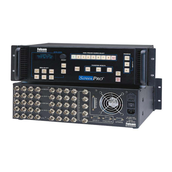
Installation Rear Panel Connectors NOTE: Front Panel features are shown in Chapter 3. ® R/CR B/CB 100-240 V 47-63Hz, 3.5A MAIN 1 Model SPR-2000 MAIN 2 PREVIEW Display Lock Figure 2-1: ScreenPro Rear Panel (Bottom Unit shown with Optional Display Lock feature installed) Manual # 26-0002901-00 / Revision H ScreenPro - High Resolution Seamless Switcher... -
Page 19: Rack-Mount Installation
Rack-Mount Installation ScreenPro units are designed to be rack mounted and are supplied with front rack-mount hardware. Rear rack- mount brackets are available as a kit and are recommended for use when units are mounted in transit cases. When rack mounting the unit, remember that maximum ambient operating temperature for the unit is 40 degrees C. Leave at least one inch of space front and rear to make sure that the airflow through the fan and vent holes is not restricted. -
Page 20: Video Input Connections
Video Input Connections The video input section on the ScreenPro rear panel provides eight universal inputs. Each input can accept RGB, YUV, S-Video (Y/C), or composite (NTSC or PAL) video signals. The connections for each input channel are made via five BNC connectors. Connection points for each type of video signal are specified below. Format –... -
Page 21: Rs-232/485 Remote Control Connections
RS-232/485 Remote Control Connections The RS-232 or RS-485 serial port can be connected to a computer to support remote control of the ScreenPro unit. The Electronics Industry Association (EIA) has produced standards for RS232 and RS485 that deal with data communications. -
Page 23: Chapter Three
CHAPTER THREE Operation What you will find in this chapter… Front Panel Controls Restarting the Program Menu Operation RBG, S-Video, Composite, Beta, MII, and EBU Color Balance, and Processing Submenus Output Setup Menu Program Step Menu Input Setup Menu Effects Menu PIP Operation Keying Operation Manual # 26-0002901-00 / Revision H... -
Page 24: Operation
Operation Front Panel Controls NOTE: Rear Panel features are shown in Chapter 2. Figure 3-1 ScreenPro Front Panel 1 Menu Select 2 Preview and Main Source Select 3 Transition Effect Keys 4 Menu Adjust/Select/Prev Menu 5 Program Setup 6 Program Step 7 Freeze Manual # 26-0002901-00 / Revision H ScreenPro - High Resolution Seamless Switcher... -
Page 25: Power Up Initialization
The menu displays the version of software that is currently being executed. The software version number will change as software upgrades are released. The most current software version is available for download from the Folsom Research web site at www.folsom.com. -
Page 26: Video Mixing And Graphics Overlay Effects (Luminance Keying)
Video Mixing and Graphics Overlay Effects (Luminance Keying) Keying Operation The operator will select the source they want as a “key/overlay” and this source will be displayed on the preview monitor. In the Effects Menu, the operator will set the WIPE TYPE to one of the key/effect types. At this point the <WIPE>... -
Page 27: Standard Wipe Transitions
Standard Wipe Transitions Curtain Wipe Transitions Dissolve Transition Freeze Effect Key To freeze the video on the Main output, press the Freeze key. The image on the Main output will freeze and the Freeze key will turn red to indicate that freeze mode has been activated. Pressing the Freeze key a second time will de-activate freeze mode and return the output to normal operation. -
Page 28: Insert Key (Ins)
Insert Key (INS) To insert a step in a pre-programmed sequence, you must first press the PROG key to enter program mode. Scroll to the number where you wish to enter the new transition using the PROG ADV or PROG REV keys. After the proper step is selected, press the INS key to activate insert mode. -
Page 29: Input Setup Menu-Standard
Input Setup Menu—Standard INPUT SETUP ACTIVE PREVIEW MENU MODE STANDARD RIGHT EDGE LEFT EDGE TOP EDGE BOTTOM EDGE CONTRAST 100.0% BRIGHTNESS 100.0% INPUT TYPE S-VIDEO LETTERBOX COLOR BAL >> PROCESSING >> UNDO CHANGES RESET CONFIG SAVE FN # SAVE AS >>... -
Page 30: Letterbox Mode
Letterbox Mode This menu item is applicable to all NON-RGB sources as well as RGB HDTV type sources. For any of these video types, a selection of OFF or ON becomes available. When set to OFF the image will be allowed to fill the entire output raster. - Page 31 ENC COLOR BALANCE SATURATION 100.0% HUE (DEGREES) 0° R CONTRAST 0.0% R BRIGHT 0.0% G CONTRAST 0.0% G BRIGHT 0.0% B CONTRAST 0.0% B BRIGHT 0.0% RESET ALL To perform adjustments, scroll to the desired menu line, select the menu item with the Select key and then turn the Adjust control to select the desired saturation or hue level while viewing the output screen.
-
Page 32: Processing
Processing The Processing menu line is used to call up a submenu to control input sync selection, DC restoration and de- interlacer functions. Scroll to the Processing menu line and press the Select key to display the Processing submenu. The Processing submenu is described in Chapter 3. Processing Submenu The Processing menu line is used to call up a submenu. -
Page 33: Undo Changes
PRE-PIPPED? This menu asks the question, is the source Pre-Pipped (or Pre-Processed). In other words, is the source coming from the output of another scaling device. If it is and if the other device is locked to the output timing of the ScreenPro, then this option, when set to “YES”... -
Page 34: Input Setup Menu, Advanced Mode
Input Setup Menu, Advanced Mode When the Input Setup key is pressed and the Advanced Menu Mode is selected. The Input Setup Menu will appear as illustrated below. Menu items that differ from the standard Input Setup Menu are in bold print. The Advanced Input Setup Menu is intended for use by experienced operators only. -
Page 35: Auto Config
Auto Config When the Auto Config menu item is activated, the unit examines the incoming video and automatically configures the system for 1:1 pixel sampling. Parameters in the H TOTAL, PHAS MAIN, PHASE PREVIEW, POSITION (R), and WIDTH (L) menu fields are calculated and loaded as part of the Auto Config process. To activate Auto Config mode, scroll to the Auto Config menu and press select. -
Page 36: Output Setup Menu
Output Setup Menu The Output Setup Menu allows the operator to select the desired output format as well as to control the output of the internal test pattern generator. OUTPUT SETUP FORMAT 1024x768 FRAME RATE XX.XXHZ SYNC PREVIEW -H-V SYNC MAIN1 -H-V SYNC MAIN2 -H-V... -
Page 37: Raster Box
Raster Box The Raster Box menu item allows the user to overlay a border on the Main or Preview output images. To control the display of the Raster Box, scroll to the Raster Box menu line, select the menu item with the Select key and then turn the Adjust control to select the desired output (Preview, Main, Both, or Off). -
Page 38: Saving Output Configuration
OFF and the Slave units are set to ON. After a few seconds, the output screens will stabilize and the systems will be locked together. When this feature is not present in the unit, the DISPLAY LOCK field will show N/A. If you wish to upgrade your unit with this Display Lock feature, contact the factory for more information. -
Page 39: Effects Menu
Effects Menu The Effects Menu allows the user to adjust the effect duration for dissolve and wipe transitions as well as to select the type of wipe transition to be performed. EFFECTS WIPE TYPE RIGHT EDGE ADJ 16 PIX KEY THRESHOLD WIPE TIME DISSOLVE TIME PIP H SIZE... -
Page 40: Pip H Size / Pip V Size
PIP H Size / PIP V Size To control the Horizontal or Vertical Size of the PIP, select the PIP H SIZE or PIP V SIZE menu item and then turn the Adjust control to the size desired, between 1% and 100%. Please make note of the following when adjusting the Horizontal or Vertical size. -
Page 41: Delete A File
Delete A File To delete an input configuration file, scroll to the Delete A File menu item and press Select to enter the Delete A File submenu. Scroll down to the File and select the menu item. Use the Adjust knob and the Select key to choose the file to delete and then scroll down to delete and select the menu item to delete the selected file. -
Page 42: Config Serial
Config Serial Allows the user to change ECHO from ON/OFF. BAUD RATE can be adjusted from 1200, 9600, 19.2K and 38.4K. DATA BIT has the option of 7 or 8. STOP BIT can be changed between 0 and 1. PARITY supports NONE, EVEN or ODD. -
Page 43: Backlight Menu
Backlight Menu Allows the user to choose whether the display buttons are lighted or not. SP+ Ext Control Menu Allows the user more flexibility when using a ScreenPro with a ScreenPro PLUS. User has the option between STANDALONE, SP+ EXT ID #2, SP+ EXT ID #3, SP+ EXT ID #4, SP+ EXT ID #5, SP+ EXT ID #6, SP+ EXT ID #7, or SP+ EXT ID # 8. -
Page 44: Factory Reset Submenu
Factory Reset Submenu DELETE ALL USER FILES AND RESET? <SELECT> = <PREV MENU> = Pressing the Select key will perform a factory reset. Pressing Prev Menu key will return the user to the previous menu. Manual # 26-0002901-00 / Revision H ScreenPro - High Resolution Seamless Switcher... -
Page 45: Chapter Four
CHAPTER FOUR Serial Command Syntax Spec’s What you will find in this chapter… Serial Parameters RS-232/RS-485 Mode Download CFG/Upload CFG Manual # 26-0002901-00 / Revision H ScreenPro - High Resolution Seamless Switcher... -
Page 46: Serial Command Syntax Specification
Serial Command Syntax Specification Serial Parameters The following are the parameter settings for serial communication. Baud Rate is 38.4. Parity is NONE. Stop Bit is 1. Data Bit is 8. Echo is ON or OFF. (Applies to RS232 mode only) For RS-232/485 signal connections, refer to Chapter 2 –... -
Page 47: Rs485 Mode
RS485 Mode Single commands will be combined with a command delimiter start, device number, command separator and command delimiter end to form a command string as shown below: Single Command Format: cdsidcmd arg1 arg2 ..argncde Multiple Command Format: cdsidcmd arg1 arg2 ..argn,idcmd arg1 arg2 ..argn,…,idcmd arg1 arg2 ..argncde cds is the command delimiter start character '*' (ASCII 42). -
Page 48: Upload Cfg
This command will download a configuration file from the ScreenPro to the serial port. The download begins immediately after the command is initiated. The user should verify that the CFG is valid before downloading. The format of the CFG data is <SOH><LIB><Index><Size><BINARY DATA><Sx>... -
Page 49: Transition Type Values
Transition type values The program transition type can have any of the following values. Dissolve Note: A Cut is a dissolve of 0.0 seconds Wipe Right Wipe Left Wipe Down Wipe Up Curtain Open Curtain Close Mosaic Example: 12410.029551.2 defines a two-sequence program file with a cut to source 2 at step 1 and a wipe-up transition of 1.2 seconds to source 9 (BLK key) with an edge with of 8 pixels at step 2. -
Page 50: Chapter Five
CHAPTER FIVE Remote Commands What you will find in this chapter… Remote Commands ScreenPro Command List/Description Terminal Remote Control Manual # 26-0002901-00 / Revision H ScreenPro - High Resolution Seamless Switcher... -
Page 51: Remote Commands
Remote Commands All commands with sclr allow either Scaler [A] or Scaler [B] to be selected. If this parameter is not used, Scaler A is used as the default. Inquiry commands will accept the scaler as an optional parameter. The default is to return information for Scaler A. -
Page 52: Screenpro Tm Command List/Description
T nnn T-Bar transition: nnn[0-255] where 0=Scaler B 255=scaler A TBLS n Terminal Backlight Status (Front Panel Switches): n[0|1] OFF|ON TCM n Terminal Remote Control Mode: n[0|1] Folsom|FSR TDI n Terminal Display Intensity: n[25|50|75|100] SYSTEM USE ONLY TER +/- nnn... -
Page 53: Debug Mode Status
Debug Mode Status DEBUG? Description: Returns the status of Debug Mode. Parameters: None Example: DEBUG? : 0 = Debug Mode Disabled; 1 = Debug Mode Enabled Download Input File /Program Sequence Configuration Description: Download input file configurations or a Program Sequence from the ScreenPro. Parameters: op - Input configuration or Program Sequence;... -
Page 54: Input Brightness Value
HELP Description: Displays the list of available command on a terminal emulator. Parameters: i – Alphabetical Index [A – Z]; Optional Parameter Example: HELP?: Returns the command list. HELP P?: Returns the entire command list starting with the first command that starts with “P”. Input Brightness Value IBRT op nnn sclr Description:... -
Page 55: Input Contrast Adjust
Input Contrast Adjust ICNT op nnn sclr Description: Adjusts the Input Contrast values. Parameters: op - Select Contrast Control; [C|R|G|B] Common, Red Offset, Green Offset, Blue Offset nnn - Contrast value, C Range 75 - 125%, RGB Range -25 - 25% sclr - Scaler [A|B|M|P];... -
Page 56: Input Clock Per Line Adjust
Input Clock Per Line Adjust ICPL op sclr nnnn Description: Adjust the number of Input Clocks per Line. Parameters: op - [A|D|M|I] Automatic | Debug | Manual | Increment Note: Debug Mode is for Factory Use Only sclr - Scaler [A|B|M|P]; Scaler A | Scaler B | Main | Preview nnnn –... -
Page 57: Input Configuration Save
Input Configuration Save ICSAV nn s[8] sclr Description: Saves an Input Configuration to a specified index. Parameters: nn - Input Configuration Index; n[1 - 64] s[8] - Input Configuration Name; s[Name] (Up to 8 characters, no spaces) sclr - Scaler [A|B|M|P]; Scaler A | Scaler B | Main | Preview Example: ICSAV 1 TEST A: Saves the input configuration currently on Scaler A to Index #1 with the label name TEST. -
Page 58: Input Horizontal Width Inquiry
Input Horizontal Width Inquiry IHW sclr? Description: Input Horizontal Width Inquiry. Parameters: sclr - Scaler [A|B|M|P]; Scaler A | Scaler B | Main | Preview Example: IHW A?: Returns the total pixel width of the input on Scaler A. Input Raster Size/Position IRSP op nnn sclr Description: Adjusts the Input Raster Size/Position. -
Page 59: Keying Command
Keying Command KEY <MODE> <SCLR> <THRESHOLD> MODE K’ = Key Mode On, ‘X’ = Key Mode Off or ‘W’ is window mode for use with PIP (PIP command does this automatically). SCLR ‘A’,’B’,’P’ or ‘M’. ‘P’/’M’ stand for preview and main. THRESHOLD 0-100%. -
Page 60: Loader Mode
Loader Mode LOADR Description: Places unit into loader mode. This mode is used to perform field upgrades. Parameters: None. Motion Adaptive De_interlace Bypass MADB n sclr Description: Bypass the Motion Adaptive De-Interlacing feature. This will reduce delay thru the system. This feature is particularly effective when using live camera sources. -
Page 61: Output Resolution Select
Output Resolution Select Command: OCRECF n <saveFlag> Description: Select the Output Resolution to use. Parameters: n - Output Resolution: n[0 – 10]; VGA|SVGA|XGA|720p|SXGA|1280x768|1365x768|1365x1024|1024x768 II|1280x1024 II|1280x960 <saveFlag> - OPTIONAL PARAMETER 0 = Do NOT Save selected output resolution to Flash memory 1 = Save selected output resolution to Flash memory (Default when this parameter is not specified.) Example: OCRECF 2: Select output format to be XGA. -
Page 62: Output Test Pattern Enable
Output Sync Adjust Command: OSYNC n op <saveFlag> Description: Adjusts the Output Sync type for any of the three outputs. Parameters: n - Output Sync: n[1-5], -C|+H+V|+H-V|-H+V|-H-V op - Output connector to make the change on: [B|H|P], where B = BNC Output connector H = Main HD15 Output connector P = Preview HD15 Output connector <saveFlag>... -
Page 63: Pip Command
PIP Command Command: PIP <ENA> <SCLR> <HSTART> <HWIDTH> <VSTART> <VWIDTH> ‘1’ is on, ‘0’ is off. SCLR ‘A’,’B’,’P’ or ‘M’. ‘P’/’M’ stand for preview and main. HSTART Horizontal start position as a percentage of the output resolution in 1% steps. Range 0 to 100. -
Page 64: Router Preview Input Switch
Router Preview Input Switch Command: RTE n op Description: Switches the router preview input. Parameters: n - Select source to route: n[1-9] where 9 = BLK op - Output to which the source is routed: op[M|P] Main | Preview Example: RTE 4 P: Switches the Preview to router input 4. -
Page 65: Setup Screenpro To Screenpro Plus
Control section of this document for further information. Parameters: n - [0|1] Folsom/Vista | FSR Example: TCM 0 : This will place the system into the Folsom/Vista remote control mode. Terminal Display Intensity Command: TDI n Description: Sets the display to the specified intensity. Intensity values are 100, 75, 50, or 25 representing a percentage of full intensity. -
Page 66: Terminal Front Panel Encoder Select
Terminal Front Panel Encoder Select Command: TER nnn Description: Allows a remote control unit to emulate the function of the encoder knob on the front panel. Parameters: nnn - [-100 - 100] Absolute value determines the speed at which the knob is rotating and must be greater than 2. -
Page 67: Terminal Led String Status
Terminal LED String Status Command: TLSR Description: Returns a 78 byte ASCII string indicating the status of the Front Panel LEDs. Parameters: None. Example: TLSR: Refer to the Terminal Remote Control section of this document for further information on the format of this string. Test Pattern Mode Command: TPMODE n (See the OTPM command in order to change the Test Pattern displayed) Description:... -
Page 68: Upload Input File Configuration
Upload Input File Configuration Command: UL Description: Upload Input File configurations or a Program Sequence to the ScreenPro. Parameters: op - Input configuration; [I|P] nn - Index Number; [0-64] s[8]- Used to override description of file uploaded. Example: UL I 2 : Upload input configuration to index 2. UL I 0 : Upload input configuration to the index it originated from. -
Page 69: Window Command
Window Command sclr hcenter hwidth vcenter vwidth Command: WIN pipen Description: sed for zooming output video when the input video’s Similar to PIP command. Command u horizontal width or vertical width is greater than 100. Parameters: pipen - [1/0] enable or disables PIP sclr - [A/B] scaler to apply this command hcenter –... -
Page 70: Terminal Remote Control
RS232 and RS485. Second is the FSR protocol. This protocol is an extension of the Folsom protocol. It allows controllers to receive the “background” commands that are sent to the Front Panel in order to keep its LED’s and Display updated whenever switches are pressed or the knob is turned. -
Page 71: Front Panel Led Status
FRONT PANEL LED STATUS LED Status Request <TLSR > Description: Issued by the Remote Controller to request that the Graphics board return the current LED status of the Front Panel. The Graphics board returns a 78-byte string that indicates the status of all LEDs. -
Page 72: Protocol Independent Commands
PROTOCOL INDEPENDENT COMMANDS The following commands can be sent to the ScreenPro regardless of the protocol selected. External Key Code <TKC KeyCode> Description: Issued by the Controller to send the “keycode” (see Table 2) for the currently pressed key or key combination. Note: “KeyCode”... -
Page 73: Terminal Encoder Rate
Terminal Encoder Rate <TER n [-100 to 100]> Description: Allows a remote control unit to emulate the function of the encoder knob on the front panel. Absolute value determines the speed at which the knob is rotating and must be greater than 3. -
Page 74: Display Put Character
Example: TDPC 0 0 ? – places a question mark at the upper left corner of the display. Note: Special display characters are specified with hexadecimal codes. Contact Folsom Research Inc. for a description of these special characters. Display Put String <TDPS row column string>... -
Page 75: Chapter Six
CHAPTER SIX SPR-2000 Software Upgrade Instructions What you will find in this chapter… Overview Preparing to Upgrade ScreenPro Unit Manual # 26-0002901-00 / Revision H ScreenPro - High Resolution Seamless Switcher... -
Page 76: Spr-2000 Software Upgrade Instructions
SPR-2000 Software Upgrade Instructions Overview The ScreenPro units built by Folsom Research, Inc. incorporate the system software in a Flash memory component. Flash memory allows easy upgrades without the need to send the unit back to the factory due to software changes. - Page 77 1) Plug the DB-25 male connector into the port labeled "Remote" on the back of the Screen Pro unit. 2) Make sure the other end of the cable is attached to the available COM port on the back of the computer performing the upgrade. 3) In the loader program, click on the Configuration Menu and select RS232 Setup.
-
Page 78: Chapter Seven
CHAPTER SEVEN Folsom Research Information What you will find in this chapter… Warranty RMA Information Technical Support/General Contact Information Manual # 26-0002901-00 / Revision H ScreenPro - High Resolution Seamless Switcher... -
Page 79: Folsom Research Information
(drop/crush), and/or other unusual damages. The customer shall pay shipping charges when unit is returned for repair. Folsom Research will cover shipping charges for return shipments to customers. - Page 81 APPENDIX Technical Specifications Manual # 26-0002901-00 / Revision H ScreenPro - High Resolution Seamless Switcher...
-
Page 82: Technical Specifications
Technical Specifications Video Input Connectors: (40) BNC Router Input Channels: 8. Video Bandwidth: 350 MHz. Input Sync Signals: Sync-on-Video; Separate C or H, V. Connections: BNC. Video Inputs High-Resolution Computer Video: Supports conversion of RGB computer video with horizontal scan rates up to 100 KHz and resolutions up to 1600x1200. -
Page 83: Remote Control
Freeze Key: A single illuminated key used to freeze the image on the main output. Setup Controls: A vacuum fluorescent display, control knob, and (8) keys provide a menu-based front panel interface to support all setup functions. Remote Control Reconfigurable RS-232/485 DB-25 port for real-time control. Physical Height: 5.25"...
Need help?
Do you have a question about the ScreenPro SPR-2000 and is the answer not in the manual?
Questions and answers