
Related Manuals for VocoPro PA-PRO 900


Summary of Contents for VocoPro PA-PRO 900
- Page 1 PA-PRO 900 -PRO 900 900W PROFESSIONAL P.A. 900W PROFESSIONAL P.A. MIXER MIXER...
-
Page 2: Table Of Contents
Table of Contents Safety Instructions ....3 FCC Information ....4 Welcome..... 5 Listening for a Lifetime . -
Page 3: Safety Instructions
Safety Instructions 8. Ventilation - The appliance should be situated so its location does not interfere with its proper ventilation. CAUTION For example, the appliance should not be situated on a bed, sofa, rug, or similar surface that may block the RISK OF SHOCK ventilation slots. -
Page 4: Fcc Information
�� To ensure the finest performance, please read this requirements. Modifications not expressly approved by manual carefully. Keep it in a safe place for future Vocopro may void your authority, granted by the FCC, reference. to use this product. �� Install your unit in a cool, dry, clean place - away from ��... -
Page 5: Welcome
Welcome And thank you for purchasing the PA-PRO 900 from VocoPro, your ultimate choice in vocal entertainment! With years of experience in the music entertainment business, VocoPro is a leading manufacturer of vocal equipment, and has been providing patrons of bars, churches, schools, clubs and individual consumers the opportunity to sound like a star with full-scale club models, in-home systems and mobile units. -
Page 6: Listening For A Lifetime
Now itʼs time to consider how you can maximize the fun and excitement your equipment offers. VocoPro and the Electronic Industries Associationʼs Consumer Electronics Group want you to get the most out of your equipment by playing it at a safe level. One that lets the sound come through loud and clear without annoying blaring or distortion and, most importantly, without affecting your sensitive hearing. -
Page 7: Features
Features Features • 450W + 450W RMS Power Output (4 ohms) • 8 Channels (4 Mic/Line, 4 Stereo/Line) • Mic/Line Channel Inputs: ¼”, XLR • Stereo/Line Channel Inputs: 1/8”, L/R RCA, L/R ¼” • Independent Tone, Level and Effect Controls on All Input Channels •... -
Page 8: Hookup Diagrams
Hookup Diagrams �������� � ���� ����� ���������� ������� ����� ��� ������ ��� ��� ������������ ������� �������� ����� �������� ����������� ������ ��������... - Page 9 If there is a need to connect a laptop or other stereo music source, you can connect to the designated stereo inputs on channels 5/6-7/8. For power output in this example, the PA-PRO 900 is configured for MAIN L/R+MONITOR output. A pair of passive speakers is powered via the MAIN L./R speaker connector.
- Page 10 Hookup Diagrams �������� � ���� �� � ���� ����� ��� ������ ��� ��� ��������� ��� ��� ��� �� ������� �������� ��������� ����� ����������� �������� ������� ������ ������ �� ��� ������...
- Page 11 Note that, you will need special insert cables connections. in order to make these connections. For output needs, you can have the PA-PRO 900 configured For output needs, you can configure the PA-PRO 900 for for standard two-channel stereo output via the POWER AMP standard two-channel stereo output with the POWER AMP ASSIGN button.
- Page 12 Hookup Diagrams �������� � ���� �� � ���� ����� ��� ������ ��� ��� ��������� ������ �� ��� ������ �����������...
-
Page 13: Hookup Diagrams
If connecting a single mono signal to either CH. 5/6 or CH. 7/8, connect to the L(MONO) jack. For power output, this example shows PA-PRO 900 configured for MAIN L/R+MONITOR output. A pair of passive speakers is powered by the MAIN L./R speaker connector. -
Page 14: Rear Panel Features
There are two types of 1a. NOTE: Before plugging in to a power receptacle, make connector available: speakon and ¼” TS. sure that voltage of your PA-PRO 900 is the same voltage Speakon outputs are wired PIN 1+positive (hot), and PIN 2-negative (cold). -
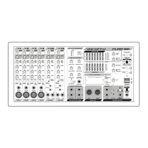
Page 15: Front Panel Features
Front Panel Features 3. DSP/REV AUX – These controls adjust the amount of 3. DSP/REV AUX – These controls adjust the amount of 3. DSP/REV AUX DSP effects applied individually to channels 1-8. This allows you to set more DSP effects to the microphone channels, and less to channels with instruments connected. - Page 16 � �� Front Panel Features � �� � � �� �� � �� �� PATCH BAY that devices can be connected to all three sets of jacks per channel simultaneously, however, there is no way to MIC/LINE (CH 1-4) individually mix the audio levels from each device. Effects can The MIC/LINE inputs are for connecting microphones, be applied to the stereo channels using the ¼”...
- Page 17 Front Panel Features COMPRESSOR (CH.1-4) Channels 1-4 have on-board compression available for preventing unwanted distortion in the audio signal. The �� compressor works by setting a threshold level with the threshold knob. Once a signal level exceeds that threshold, the signal is automatically compressed. Compression is very ��...
- Page 18 Front Panel Features 18. ECHO DELAY – This control is used to adjust the 18. ECHO DELAY – This control is used to adjust the 18. ECHO DELAY 23. FOOT SW. – This input jack is for connecting an length of time between each echo repetition. When set to external footswitch that can be used to enable or disable minimum, the echo repetitions will occur rapidly, with little to DSP effects.
- Page 19 Front Panel Features �� �� �� �� �� �� � � �� 25. MAIN L, R GRAPHIC EQ – This 7-band graphic EQ 25. MAIN L, R GRAPHIC EQ – This 7-band graphic EQ 25. MAIN L, R GRAPHIC EQ 28.
- Page 20 �� �� �� �� Front Panel Features � � �� � �� �� �� �� �� � 29. MONITOR GRAPHIC EQ – This 7-band graphic EQ is 29. MONITOR GRAPHIC EQ – This 7-band graphic EQ is 29. MONITOR GRAPHIC EQ used to customize the sound of the MONITOR mix output.
- Page 21 MUTE LED will remain lit until mute is disabled. 33. +48V PHANTOM POWER – This button toggles phantom power to all the XLR microphone jacks. Enabling 37. POWER – Use this switch to power the PA-PRO 900 phantom power sends low current DC voltage to a ��...
- Page 22 �� �� Front Panel Features �� �� �� �� �� �� �� Master Out Panel 42. MONO/SUBWOOFER – This ¼” jack can be used to send a line-level signal suited for subwoofer connection, The master out panel is where you make output connections or a mono signal of the main mix.
-
Page 23: Optional Accessories
PA-PRO 900. This LED should 4. NEXT BUTTON – This button will skip forward through illuminate and stay lit as long as the PA-PRO 900 is powered previously recorded tracks. When the last track recorded is reached, it will continue to skip forward from the first... - Page 24 Optional Accessories 9. SD CARD SLOT – Insert your SD card into this slot. The SDR-3 will not record without an SD card in this slot. 10. REC LEVEL LEDs – These LEDs visually represent the gain level of the signal being recorded. There are five green LEDs and two red LEDs.
-
Page 25: Optional Accessories
You can add up to four UHF wireless microphone modules 3. Align the cover plate, and tighten screws. (sold separately) to use with the PA-PRO 900. Each port on the rear panel corresponds to a mic channel on the front Antenna Installation panel. -
Page 26: Technical Specifications
Technical Specifications PA-PRO 900 SPECIFICATIONS Mixer Input (AT MAIN L/R OUTPUT +4dBu,1kHz) Specifi cation INPUT CONNECTION LEVEL(RATED INPUT) TOTAL GAIN IMPEDANCE MIC INPUT XLR (BAL) -50dBu 54dB 1 Kohm CH1-CH4 1/4” TRS (BAL/UNBAL) -20dB(PAD ON) 24dB MUSIC LINE 1/4”TRS(UNBAL) -22dBu 26dB 2.8Kohm... - Page 27 Technical Specifications Frequency Response (AT MAIN L/R OUTPUT +4dBu) MIC INPUT /CH1-4 10Hz-24kHz 0dB / -1.5dB STEREO INPUT/ CH5-8 10Hz-35kHz 0dB / -1.5dB Channel EQ CH1-8 EQ HIGH 100Hz ±15dB 2.5kHz ±12dB 10kHz ±15dB 7-Band Graphic EQ MAIN L/R OUTPUT (XLR/BAL) 125Hz ±12dB MONITOR OUTPUT (1/4”...
- Page 28 Technical Specifications Hum & Noise(S/N) OUTPUT LEVEL CONDITION AMP OUTOUT < -80 dB 1/2POWER 1kHz LEFT/RIGHT STEREO LOOP RETURN IN MIC TO MAIN MIX OUTPUT < -74 dB MIC LEVEL CENTER, MAIN VR +4dB ADJ EQ CENTER, INPUT -30dB AUX/MONITOR OUTPUT <...
- Page 29 Technical Specifications Maximum Input Level INPUT CONNECTION LEVEL MIC INPUT XLR (BAL) -20dBu CH1-CH4 1/4” TRS (BAL/UNBAL) +10dB(PAD ON) STEREO LINE 1/4”TRS(UNBAL) -0dBu CH5/6-7/8 CD RCA STEREO(UNBAL) -0dBu MP3 1/8” PHONE(UNBAL) -2dBu TIP:L,RING:R EFFECT Controls (D.S.P) REVERB/DELAY CONTROL ECHO DELAY 40mS-242mS ECHO REPEAT 30%-80%...
-
Page 30: Notes
Notes... -
Page 31: Troubleshooting
• If using a power strip/surge-protector, make sure that it is plugged in and switched on. • Check the fuse, and replace if blown. If the fuse blows again immediately, do not replace it again. Instead, contact VocoPro technical support. There is no sound •... - Page 32 PA-PRO 900 Owner’s Manual © VocoPro 2010 v1.1008 www.vocopro.com...
Need help?
Do you have a question about the PA-PRO 900 and is the answer not in the manual?
Questions and answers