
Summary of Contents for Drawmer LX20
-
Page 1: Table Of Contents
FIRST TIME USER page 3 SYSTEM OPERATING LEVELS page 3 FRONT & REAR PANEL LAYOUT page 4 OPERATION page 5 REAR PANEL CONNECTIONS page 6 TECHNICAL SPECIFICATION page 7 LX20 CHARACTERISTICS page 8 BLOCK DIAGRAM page 9 DRAWMER ELECTRONICS LTD. 1988... - Page 2 COPYRIGHT This manual is copyrighted © 1988 by Drawmer Electronics, Ltd. With all rights reserved. Under copyright laws, this manual may not be duplicated in whole or in part without the written consent of Drawmer. UPGRADES In the interests of product development, Drawmer reserve the right to modify or...
-
Page 3: Safety Considerations
LX20 OPERATOR’S MANUAL DRAWMER LX20 Dual Expander/Compressor SAFETY CONSIDERATIONS CAUTION - MAINS FUSE TO REDUCE THE RISK OF FIRE REPLACE THE MAINS FUSE ONLY WITH THE SAME TYPE, WHICH MUST BE A CLASS 3, 230 VOLT, TIME DELAY TYPE, RATED AT 32mA WHERE THE MAINS INPUT VOLTAGE SWITCH IS SET TO 230 VOLTS AC. -
Page 4: Installation
This is used to make the compressor section respond in different ways to various frequencies, which is useful for ‘de-essing’. Another useful feature of the LX20 is the mute facility. This enables each channel to be shut off... -
Page 5: First Time User
SYSTEM OPERATING LEVEL The LX20 is capable of operation at system levels of +4dBu and !10dBu and is supplied from the factory set to +4dBu. Your dealer will be able to advise you regarding system level and make any changes that are necessary. -
Page 6: Front & Rear Panel Layout
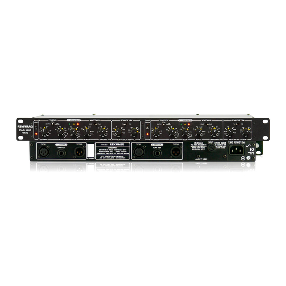
LX20 OPERATOR’S MANUAL FRONT & REAR PANEL LAYOUT 1) Expand LED. This illuminates at the onset of expansion. 2) Compression indication. Moves from right to left during compression. 3) Mute LED. When on, channel is disabled except in Bypass. 4) VU indication. -
Page 7: Operation
OUTPUT With the LX20, increasing compression also increases the output level, which is then adjusted by the output control to compensate for the increase. A simple LED array gives indication of signal levels in volume units (VU). This enables the output to be adjusted to the required level. -
Page 8: Rear Panel Connections
LX20. When muted, no matter what signal is present at the input the output will be silent. WHEN THE LX20 IS USED WITH THE STEREO LINK ON, BOTH MUTE SOCKETS SHOULD BE OPERATED... -
Page 9: Technical Specification
LX20 OPERATOR’S MANUAL TECHNICAL SPECIFICATIONS SYTEM OPERATING LEVEL !10dB OR +4dB, selected by internal switches INPUT IMPEDANCE 47 Kohms unbalanced OUTPUT Unbalanced NOISE @ unity gain !85dB (22Hz to 22KHz) MAX GAIN 40dB DISTORTION @ unity gain Less than 0.3% DISTORTION @ 10dB compression Less than 0.3%... -
Page 10: Lx20 Characteristics
LX20 OPERATOR’S MANUAL LX20 CHARACTERISTICS... -
Page 11: Block Diagram
LX20 OPERATOR’S MANUAL BLOCK DIAGRAM...
Need help?
Do you have a question about the LX20 and is the answer not in the manual?
Questions and answers