Advertisement
Quick Links
MCR-304
Wireless Interface for Hard-Wire Control Panels
1. INTRODUCTION
1.1 Purpose and Use
The MCR-304 is a single output wireless
PowerCode / CodeSecure™ receiver designed
to add fully supervised wireless capabilities to
hard-wired control panels, as demonstrated in
Figure 1.
The MCR-304 can be connected to various
control panels for remote control purposes and
can use up to 10 Powercode / CodeSecure™
wireless devices for remote control.
The MCR-304 will recognize only those
devices with IDs that have been "taught" into its
non-volatile memory. Other devices will be
ignored.
Detailed
teaching/learning
Paragraphs 3.4 and 3.5.
The MCR-304 provides trouble, low battery and tamper outputs
which are common to all 10 wireless devices.
1.2 Control Output
The MCR-304 features a single FORM-1C relay output that
reacts to control signals received from up to 10 wireless detectors
or hand-held transmitters. The relay can be programmed to
operate in the Pulse or Toggle modes (see Para. 4.4 for full
details).
WIRELESS
POWERCODE OR
CODE-SECURE
TRANSMITTERS
AND DETECTORS
(UP TO 10 UNITS)
Figure 1. Typical Application of the MCR-304
1.3 Status Outputs
In addition to the single relay output, the MCR-304 provides 3 open-
collector status outputs that function as follows:
Tamper: This output is activated once a TAMPER state is
detected in a transmitter or in the MCR-304 receiver itself.
Low Battery: This output is activated whenever a low battery
message is received from one of the detectors/transmitters.
2. SPECIFICATIONS
RF SECTION
Front-End Module: Super-regenerative UHF receiver.
Operating Frequency: Per local requirements in country of use.
DATA PROCESSING SECTION
ID codes: Over 16,000,000 possible 24-bit combinations.
Total Message Length: 36 bits (66 bits for code secure devices)
ID Learning Capacity: Up to 10 different ID codes
ELECTRICAL DATA
Relay Outputs: Form 1C (N.C. and N.O.)
Relay Contact Ratings: 1A resistive, 30 VDC or AC.
Status Outputs: 3, up to 100 mA each, open-collector type
Relay Output Modes: Pulsed (3 s) or toggle, jumper selected.
DE3174
procedures
are
provided
HARD-WIRED
MCR-304
CONTROL PANEL
RECEIVER
REMOTE CONTROL
RELAY OUTPUT
ZONE INPUT
TROUBLE OUT
24 HR TROUBLE ZONE
24 HR BATERY
LOW BATTERY OUT
SUPERVISION ZONE
TAMPER OUT
24 HR TAMPER ZONE
12V
12 VDC OUT TERMINALS
-
+
Installation Instructions
Replacing the battery in the transmitter that sent the low-battery
message and transmitting once again resets the output.
Trouble: This output is activated if a supervised transmitter fails
to send its attendance message within a 4-8 hours time frame.
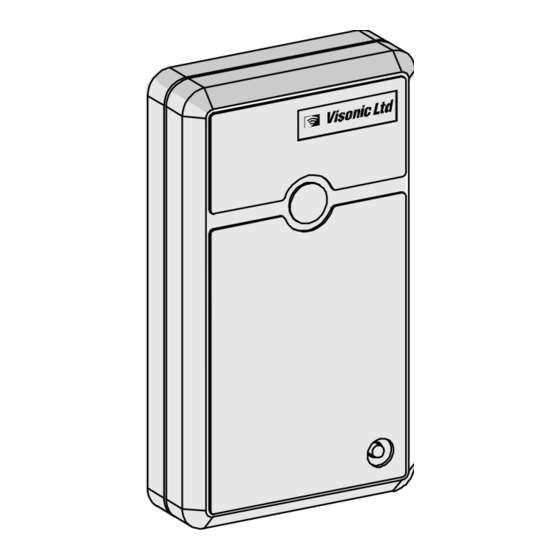
1.4 Construction Details
For construction details, refer to Figure 2.
in
Figure 2. MCR-304 with Cover Removed
1.5 Receiver Operating Modes
Two operating modes are available:
OPERATE - normal position (receiver stands by for signals)
LEARN - enrollment of transmitter IDs in the MCR-304
memory.
1.6 LED Functions during Operation
SIGNAL indicator (red - visible through a hole in the cover):
This LED illuminates when the output relay is energized and
continues to light for as long as the relay remains energized. The
LED extinguishes when the relay drops out.
Note: The red LED has a different function during the learning
session (see Paragraphs 3.4 and 3.5).
Memory Location indicator (yellow - visible only when the
cover is removed): This LED is extinguished in normal operation,
but has a special function during the "learning" session.
Tamper Switch Ratings: 0.1 A / 30 VDC.
Input Voltage Range: 10.5-16 VDC (MCR-304) or 24 VAC/DC
(MCR-304U)
Current Drain (@ 12 VDC): 7 mA (standby), 32 mA (relay
energized).
Compliance with Standards:
ETS 300683).
PHYSICAL
Operating Temperatures: 0°C to 49°C (32°
Dimensions (H x W x D): 110 x 63 x 25 mm (4-5/16 x 2-1/2 x 1").
Weight: 76 g (2.7 oz).
FCC Part 15,
CE (ETS 300220,
F to 120°
F).
¡
¡
1
Advertisement

Related Manuals for Visonic MCR-304


Summary of Contents for Visonic MCR-304
-
Page 1: Installation Instructions
Note: The red LED has a different function during the learning session (see Paragraphs 3.4 and 3.5). In addition to the single relay output, the MCR-304 provides 3 open- collector status outputs that function as follows: Memory Location indicator (yellow - visible only when the... -
Page 2: Helpful Hints
C. Click the MCR-304 tamper switch the correct number of times to select the desired memory location (see Para. 3.3.). Each A learning session is required to let the MCR-304 learn the ID click advances to the next memory location. The red LED will... -
Page 3: Product Limitations
After wiring, you must set the relay output operating mode in ZONE INPUT 12 VDC accordance with the requirements of your specific application. Note: The relay output of the MCR-304 may be used for remote NOTE: THESE control tasks such as opening / closing a garage door. CONNECTIONS... - Page 4 VISONIC LTD. (ISRAEL): P.O.B 22020 TEL-AVIV 61220 ISRAEL. PHONE: (972-3) 645-6789, FAX: (972-3) 645-6788 VISONIC INC. (U.S.A.): 65 WEST DUDLEY TOWN ROAD, BLOOMFIELD CT. 06002-1376. PHONE: (860) 243-0833, (800) 223-0020 FAX: (860) 242-8094 VISONIC LTD. (UK): 7 COPPERHOUSE COURT, CALDECOTTE, MILTON KEYNES. MK7 8NL. PHONE: (0870) 7300800 FAX: (0870) 7300801 PRODUCT SUPPORT ( 0870) 7300830 www.visonic.com...
Need help?
Do you have a question about the MCR-304 and is the answer not in the manual?
Questions and answers