Advertisement
Wireless
Wireless
Digital
Digital
Thermostat
Thermostat
Receiver
Receiver
Control up to 2 Heat &
2 Cool Stages
Wireless Operation
Receives up to 4 Thermostats
Flexible Installation Locations
May be Mounted at Old
Thermostat Location or
with the Furnace
Use with most Air Conditioning & Heating Systems including: 1 or 2 Stage
Electric Cooling & 2 Stage Gas Heating, Heat Pump, Electric or Hydronic Heat.
INSTALLATION
INSTALLATION
INSTRUCTIONS
INSTRUCTIONS
Venstar Inc. 08/07
residential
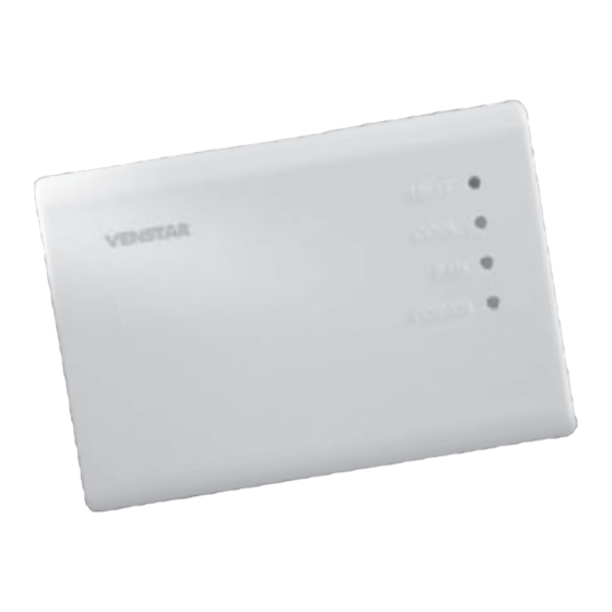
WIRELESS
THERMOSTAT
RECEIVER
T1 1 00REC
USE IN
USE IN
CONJUNCTION
CONJUNCTION
WITH T1100RF
WITH T1100RF
up to
2-heat
up to
2-heat
& 2-cool
& 2-cool
HEAT
HEAT
COOL
PUMP
Advertisement

Subscribe to Our Youtube Channel
Related Manuals for Venstar T1100REC

Summary of Contents for Venstar T1100REC
- Page 1 May be Mounted at Old Thermostat Location or with the Furnace Use with most Air Conditioning & Heating Systems including: 1 or 2 Stage Electric Cooling & 2 Stage Gas Heating, Heat Pump, Electric or Hydronic Heat. INSTALLATION INSTALLATION INSTRUCTIONS INSTRUCTIONS Venstar Inc. 08/07...
-
Page 2: Table Of Contents
Rules. Operation is subject to the following two conditions: (1) this device may not FCC ID MUH-T10016 cause harmful interference, and (2) this device must accept any interference received, including interference that may cause undesired operation. P/N T1100REC Venstar Inc. 08/07 Page 1... -
Page 3: Step #1: Preparation
STEP #1 PREPARATION Proper installation of the thermostat will be HEAT COOL POWER accomplished by following these step by step instructions. If you are unsure about any of these steps, call a qualified technician for assistance. Assemble tools. HEAT COOL POWER Drill with 3/16 inch Drill Bit... -
Page 4: Step #2 Remove & Replace Old Thermostat
STEP #2 REMOVE & REPLACE OLD THERMOSTAT Remove the cover of the old thermostat. HEAT COOL POWER If it does not come off easily check for screws. Loosen the screws holding the thermostat HEAT COOL POWER base or subbase to the wall, and lift away. Disconnect the wires from the old HEAT COOL... -
Page 5: Step #3: Dip Switch Settings
STEP #3 DIP SWITCH SETTINGS House Code Setting Antenna switches Circuit Board ON Indicator Add all of the ON switches to arrive at the House Code number. All thermostats communicating with this receiver must have the Example: same House Code number. House Code 10 If all of the number switches 2+8=10... - Page 6 Equipment Settings Heat Pump ON Indicator O or B Reversing Valve To configure the receiver for Heat Pump operation, slide the HP switch to the ON position as shown. The Reversing Valve polarity can also be set. OFF = O and ON = B.
-
Page 7: Step #4 Wire Connections
STEP #4 WIRE CONNECTIONS If the terminal designations on your old HEAT COOL thermostat do not match those on the POWER new thermostat, refer to the chart below, or the wiring diagrams that follow. Wire from the I n s t a l l t h e thermos tat thermostat... - Page 8 Sample Wiring Diagrams Gas or Electric Heat 5 Wire, 1 Stage Cooling, 1 Stage Gas Heat Residential Gas or Electric Heat*, Electric Cool, split systems & package units. COMMON COMPRESSOR GAS VALVE STRIP HEAT POWER * If using first stage electric heat, the “EH” dip switch must be set to ON (see page 5).
- Page 9 Sample Wiring Diagrams Gas or Electric Heat 4 Wire, 1 Stage Cooling, 1 Stage Gas Heat Residential Gas or Electric Heat*, Electric Cool, split systems & package units. COMPRESSOR GAS VALVE STRIP HEAT POWER * If using first stage electric heat, the “EH” dip switch must be set to ON (see page 5).
- Page 10 Sample Wiring Diagrams Gas or Electric Heat 2 Wire, 1 Stage Gas or Electric Heat Furnace Board White Brown Black 24VAC 24V Relay 200mA Orange Black Adaptor The ACC0436 Wireless Thermostat Two-Wire Kit can be purchased separately. * If using first stage electric heat, the “EH” dip switch must be set to ON (see page 5).
- Page 11 Sample Wiring Diagrams Gas or Electric Heat 6 Wire, 2 Stage Cooling, 1 Stage Gas Heat Residential two stage cooling with Gas or Electric Heat.* COMMON COMPRESSOR GAS VALVE STRIP HEAT POWER 2nd STAGE COOLING * If using first stage electric heat, the “EH” dip switch must be set to ON (see page 5).
- Page 12 Sample Wiring Diagrams Gas or Electric Heat 6 Wire, 1 Stage Cooling, 2 Stage Heat Residential & Commercial 1 Stage Cooling, with 2 Stage Gas or Electric Heat.* COMMON COMPRESSOR GAS VALVE STRIP HEAT POWER 2nd STAGE HEATING * If using first stage electric heat, the “EH” dip switch must be set to ON (see page 5).
- Page 13 Sample Wiring Diagrams Gas or Electric Heat Commercial Gas or Electric Heat*, 7 Wire, 2 Stage Cooling, 2 Stage Heat Electric Cool, split systems & package units including Commercial Heat Pumps.** COMMON COMPRESSOR GAS VALVE STRIP HEAT POWER 2nd STAGE COOLING 2nd STAGE HEATING...
- Page 14 Sample Wiring Diagrams Heat Pump 5 Wire, 1 Stage Cooling, 1 Stage Heat, Heat Pump* with O or B reversing valve**. Residential Heat Pumps, split systems & package units, with no auxiliary heat. COMMON COMPRESSOR REVERSING VALVE** POWER * The “HP” dip switch must be set to ON (see page 5). ** The “O/B”...
- Page 15 Sample Wiring Diagrams Heat Pump 6 Wire, 1 Stage Cooling, 2 Stage Heat, Heat Pump* with O or B reversing valve**. Residential Heat Pumps, split systems & package units, with auxiliary heat. COMMON COMPRESSOR REVERSING VALVE** POWER 2nd STAGE HEATING * The “HP”...
-
Page 16: Step #5 Test Operation
STEP #5 TEST OPERATION Turn the power on to the Heating/Air HEAT HEAT COOL COOL POWER Conditioning system. POWER Press the MODE button repeatedly until HEAT HEAT COOL COOL POWER the HEAT icon appears on the display. POWER Press the UP or DOWN button until the set temperature is 10 degrees above room temperature. -
Page 17: Troubleshooting
TROUBLESHOOTING SYMPTOM: When using 4 wires (R, G, W, Y), HEAT COOL the air conditioning or heating equipment POWER tries repeatedly to turn on, but cannot. CAUSE: There is not enough power available to "power share". REMEDY: Connect a 250 ohm, 10 watt power resistor at the furnace as shown below. - Page 18 (non-heat pump) system. REMEDY: See page 5 of this manual and set the Heat Pump (HP) switch to OFF to enable gas electric operation. Receiver T1100REC Tested to Comply with FCC Standards FOR HOME OR OFFICE USE 4Z95 P/N 88-615 Rev.
Need help?
Do you have a question about the T1100REC and is the answer not in the manual?
Questions and answers