Table of Contents
Advertisement
Advertisement
Table of Contents

Related Manuals for TC Electronic XO24


Summary of Contents for TC Electronic XO24
- Page 1 XO24 PEAKER ANAGEMENT ONTROLLER U U s s e e r r s s m m a a n n u u a a l l...
-
Page 3: Important Safety Instructions
IMPORTANT SAFETY INSTRUCTIONS The lightning flash with an arrowhead The exclamation point within an symbol within an equilateral triangle, is equilateral triangle is intended to alert the intended to alert the user to the user to the presence of important presence of uninsulated "dangerous volt- operating and maintenance (servicing) age"... -
Page 4: Certificate Of Conformity
Class B Digital device, pursuant to part 15 of the FCC rules. Certificate Of Conformity These limits are designed to provide TC Electronic A/S, Sindalsvej 34, 8240 reasonable protection against harmful Risskov, Denmark, - hereby declares on interference in residential installations. This... -
Page 5: Table Of Contents
TABLE OF CONTENTS INTRODUCTION Important Safety Instructions & Certificate of conformity ..a-b Table of Contents ....3 Introduction . -
Page 7: Introduction
Read through this operation manual to get more information about the specific features available in XO24, or start to use the XO24 right out of the box and get back to these pages in case you seek answers to specific features. -
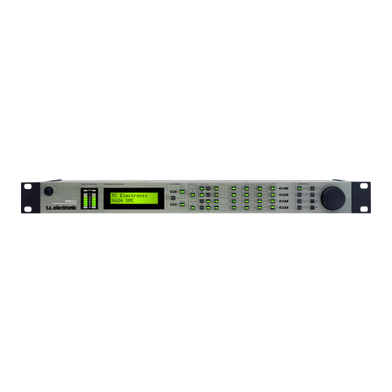
Page 8: Front Panel Overview
DIGITAL IN select distribute Input channels A/B Press the DIGITAL IN key and to any of the four Output the XO24 will try to lock to the LIMITER channels. On/Off keys for the Limiter Digital Input. If a valid digital... - Page 9 LOCK On/Off keys on the Output for The LOCK key is used to each of the four channels. lock/unlock the XO24 front panel keys. Default setting is In Edit mode these keys give “locked”. access to edit the Output level parameter.
-
Page 10: Rear Panel Overview
REAR PANEL Balanced Inputs Balanced Digital Com port for data Power Input. on XLR for Outputs 1-4 S/PDIF In transfer. The internal channels A/B. on XLR. and Thru NO user application. switchmode Use channel A on RCA powersupply accepts for mono Input. phono. -
Page 11: Signal Flow Diagram
SIGNAL FLOW... -
Page 12: Typical Setups
TYPICAL SETUPS Stereo Setup - with subs This is a typical stereo setup with a set of subs. Analog: • Input signal is fed on Inputs A/B. • Configure Routing section as illustrated below. • Output channels 1 and 2 feed the front loudspeakers. - Page 13 TYPICAL SETUPS Stereo Setup This setup is a typical small 2-way system. Analog • Input signal is fed to Inputs A and B. • Configure Routing section as illustrated below. • Output channels 1 and 2 feed loudspeaker set A. •...
- Page 14 SETUPS 3/4 way setup - Bi-Amp Mid/High This example shows how 2 XO24s can be used in conjunction to distribute Input signals to a 3 or 4 way system per side. For each side: • Source signal can be connected to either Inputs A or B as only one Input per side is used.
- Page 15 SETUPS System Distribution - with delay Configuration overview This example is similar to the previous example. However, the idea here is to distribute the signal with delay settings corresponding to the positioning of the speakers. Using the Digital Input For each side: •...
- Page 16 SETUPS Dual Source Mono - Dual Zone This setup is used where two different zones or rooms need to be covered. In this case Stereo is not the object. • Source 1 is connected to Input A and Source 2 to Input B. •...
-
Page 17: Control Section
CONTROL SECTION 4 Now you may; - either press ENTER again to confirm and end the store operation - or dial in a preset name of your choice using the CURSOR keys and ADJUST encoder and then press ENTER. 5 The display indicates “Preset Stored” for a successful store operation. -
Page 18: Front Panel Operation
Input Bypass A/B - Input Trim The XO24 accepts digital Input at 44.1 or Signal from the two Inputs A and B will be 48kHz. Per default the XO24 is set to analog passed to the Routing section if the LEDs in the Inputs. - Page 19 A typical example of a stereo setup with split in both sides. More examples on pages 10 to 13. For optimal settings please refer to your X-Over speaker specifications. The XO24 may hold presets that perfectly match your speaker configuration. X-Over A,B: Type: Gain Freq:...
- Page 20 FRONT PANEL OPERATION Parametric EQ (Speaker EQ) EQ 1-4 Type: Gain Freq: Width/Slope: Band 1 Hi Pass ±18 dB 20 Hz – 20 kHz 2nd order Par EQ ±18 dB 20 Hz – 20 kHz 0,03 – 4 Oct Band 2 Par EQ ±18 dB 20 Hz –...
-
Page 21: Appendix
APPENDIX - TECHNICAL SPECIFICATIONS Analog Inputs Connectors: Impedance, Bal / Unbal: 21 kOhm / 13 kOhm Max. / Min. Input Level @ 0 dBFS: +24 dBu / 0 dBu Sensitivity Range @ 12 dB headroom: -12 dBu to +12 dBu A to D Conversion: 24 bit, 128 x oversampling bitstream A to D Delay:... -
Page 22: Preset List
PRESET LIST The XO24 factory presets are listed below. The presets are generic and should be perceived at excellent "starting points". To achieve optimal performance of your setup, the presets probably require some adjustment and fine-tuning according to the specifications of your... - Page 23 PRESET LIST...
Need help?
Do you have a question about the XO24 and is the answer not in the manual?
Questions and answers