Table of Contents
Advertisement
Advertisement
Table of Contents

Subscribe to Our Youtube Channel
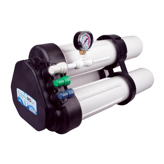
Summary of Contents for Hydro-Logic Purification Systems EVOLUTION-RO1000
- Page 1 Installation & Maintenance Manual...
- Page 2 NOTES: ___________________________________________ ___________________________________________ ___________________________________________ ___________________________________________ ___________________________________________ ___________________________________________ ___________________________________________ ___________________________________________ ___________________________________________ ___________________________________________ ___________________________________________ ___________________________________________ ___________________________________________ ___________________________________________ ___________________________________________ ___________________________________________ ___________________________________________ ___________________________________________ ___________________________________________ ___________________________________________ ___________________________________________ ___________________________________________...
-
Page 3: Safety Guides
The Reverse Osmosis System does not have a monitoring device for maintenance of the Evolution-RO1000. An optional De-Ionization contaminants. To verify that the system is performing satisfactorily post-filter will remove any remaining PPM of TDS in the water after the product water should be tested periodically by the system’s... - Page 4 THE BASIC REVERSE OSMOSIS SYSTEM cont. SUPPORT FITTINGS MEMBRANE SUMP LEG/SUMP & LOCKING BAR ELEMENT (FILTER WRENCH INSTALL KIT PN 22045 HOUSING) PN 23063 (2 pcs) & O-RING (1 pc) FEED/INLET SUMP LOCKING BAR DISCONNECT DISCONNECT ELBOW - WHITE PN 23115 PN 23075 (1 pc) PN 23061 (1 pc) (3 pcs)
- Page 5 THE BASIC REVERSE OSMOSIS SYSTEM cont. LOCATION OF SYSTEM Drain Point: A suitable drain point is needed for reject (waste) water from the RO system. A floor drain, laundry tub, standpipe, sump, etc. The reverse osmosis system can be installed under or near a sink or are all acceptable.
- Page 6 THE BASIC REVERSE OSMOSIS SYSTEM cont. Feed Pressure Gauge Feed Water Valve Cold Water Line Only Optional Pre-Evolution Pre-Filter ™ Inlet-1/2" White Drain - 3/8" Black Purified Water - 3/8" Blue 1.5" Air Gap Required Optional 3/8” Float Valve To Point of Use Pure Water Storage Tank Typical Light Commercial Installation with Storage Tank...
-
Page 7: Installation
INSTALLATION STEP 1: Install cold water supply fitting. Use either the included garden hose connector or any of the other optional feed fittings. STEP 2: Install optional drain adapter STEP 3: Make tubing connections STEP 4: Install RO assembly STEP 5: Put system into operation NOTE: Consult a licensed plumber if you are not familiar with plumbing procedures. -
Page 8: Step 3: Make Tubing Connections
INSTALLATION cont. Step 3: Make Tubing Connections The connections to the faucet should be complete, the remaining Collet connections are: Lock Clip • Feed connection—white 1/2” tubing from feed fitting or feed valve to pressure gauge and then to white elbow connector •... - Page 9 INSTALLATION cont. Recommended Placement Positions The RO assembly should be positioned in one of two ways. Support Leg Locking Bar The first position is with the unit standing upright using the support leg with the sumps horizontal. The tubing is directed to provide the best fit.
-
Page 10: Step 6: System Startup
INSTALLATION cont. The table below shows the coding system for the fitting connections. Each fitting has a unique “keyed” socket on the manifold. Each fitting also has a graphic symbol molded into the elbow with a corresponding symbol on the manifold. Connector Symbol Connection Tubing Color... - Page 11 TO CARE FOR THE RO SYSTEM The components of the RO system are designed to function with minimal maintenance. However, the membrane elements and pre- filter will need to be replaced on a regular schedule. For optimal performance the system should be flushed for 2 minutes if periods of inactivity that extend past six hours.
- Page 12 REPLACEMENT OF THE PRE-FILTER, AND RO MEMBRANE ELEMENTS cont. If changing membrane elements: Remove membrane sumps. Remove and discard used elements. Remove new elements from packaging. Membrane Element CAUTION: Elements contain a foodgrade preservative. The use of Locations sterile/latex gloves is highly recommended. Lubricate element O-rings, brine seals, and sump O-rings with silicone lubricant.
-
Page 13: Performance Specifications
Performance Specifications Minimum and Maximum Operating Conditions Condition Minimum Maximum Inlet Pressure 40 psi (2.76 bar) 80 psi (5.52 bar) Inlet Temperature F (4.44 F (37.78 ° ° ° ° Inlet TDS 50 mg/L 2,000 mg/L Inlet Hardness 0 mg/L (0 grain) 171 mg/L (10 grain) Inlet Chlorine 0 mg/L... -
Page 14: Troubleshooting
Replace RO membranes. Replace both o-rings on membrane stem and lube properly before Membrane stem o-rings damaged during installation installing Hydro-Logic Purification Systems For available options and add-ons, 370 Encinal Street, Suite 150 contact Hydro-Logic directly Santa Cruz, CA 95060 P: 888.426.5644... - Page 15 NOTES: ___________________________________________ ___________________________________________ ___________________________________________ ___________________________________________ ___________________________________________ ___________________________________________ ___________________________________________ ___________________________________________ ___________________________________________ ___________________________________________ ___________________________________________ ___________________________________________ ___________________________________________ ___________________________________________ ___________________________________________ ___________________________________________ ___________________________________________ ___________________________________________ ___________________________________________ ___________________________________________ ___________________________________________ ___________________________________________...
- Page 16 GL4000442 RevA...

Need help?
Do you have a question about the EVOLUTION-RO1000 and is the answer not in the manual?
Questions and answers