M-Audio Wayoutware TimewARP 2600 User Manual
Hide thumbs
Also See for Wayoutware TimewARP 2600:
- Quick start manual (3 pages) ,
- Getting started manual (16 pages)
Table of Contents
Advertisement
Quick Links
User Guide
English
Copyright © 2004, by Way Out Ware, Inc.. All rights reserved.
No part of this work may be reproduced or transmitted in any form or by any means, electronic or
mechanical, from or to any form of media, without the prior written permission of Way Out Ware, Inc..
Requests for permission to reproduce any part of this work should be addressed to : Way Out Ware,
Inc., attn: Copyright Adminstration, info@wayoutware.com.
Advertisement
Table of Contents

Related Manuals for M-Audio Wayoutware TimewARP 2600


Summary of Contents for M-Audio Wayoutware TimewARP 2600
- Page 1 User Guide English Copyright © 2004, by Way Out Ware, Inc.. All rights reserved. No part of this work may be reproduced or transmitted in any form or by any means, electronic or mechanical, from or to any form of media, without the prior written permission of Way Out Ware, Inc.. Requests for permission to reproduce any part of this work should be addressed to : Way Out Ware, Inc., attn: Copyright Adminstration, info@wayoutware.com.
-
Page 2: Table Of Contents
Table Of Contents The TimewARP 2600 Manual ..............3 1.1 The ARP 2600, 1970 - 1981 and Onward . -
Page 3: The Timewarp 2600 Manual
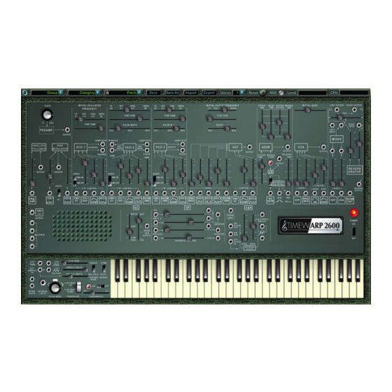
TimewARP • User Guide English The TimewARP 2600 Manual The ARP 2600, 1970 - 1981 and Onward The ARP 2600 was the second product of ARP Instruments. It was released in 1970, and continued until the manufacturer ceased operations in 1981. Its design combined modularity (for studio flexibility, and for instructional use) and integration (for real-time performance). -
Page 4: How This Manual Is Organized
How this Manual is Organized This is not a textbook; it’s a survival manual. Chapter 2 is about installing and configuring the software so you can get up and running. Chapter 3 is a brief introduction to the vocabulary and methods of classical analog synthesis, so that we can understand each other throughout the rest of the book. -
Page 5: System Requirements, Installation, Configuration, Setup And Usage
TimewARP • User Guide System Requirements, Installation, Configuration, Setup and Usage In this chapter you will find all of the platform-dependent information you need in order to install and operate your TimewARP 2600 software synthesizer. The TimewARP 2600 provides an extended set of digitally-based features that no hardware-based analog synthesizer can offer. - Page 6 2.1.3.2 Processing Audio Signals The TimewARP 2600 can be used to process audio signals in a similar manner to a reverb or other effects plug- To set this up, create an audio track or select a track already recorded in Pro Tools. (If this is a new track, select either mono or stereo in the track-creation window;...
-
Page 7: Midi Communication And Control
TimewARP • User Guide 2.1.7 Using the Virtual Keyboard Display The graphic TimewARP 2600 keyboard display responds directly to mouse events; click on any key to create a MIDI “keydown” signal. This is useful when you are creating and tuning a new patch, if you don’t have a hardware MIDI keyboard handy. -
Page 8: The Craft Of Audio Synthesis
The Craft of Audio Synthesis This chapter is about the facts—physical, mathematical, and auditory—that make the TimewARP 2600, and the hardware that it emulates, possible. We have to spend a few minutes here distinguishing between physical signals, and the sounds that people hear in the presence of certain kinds of signals. -
Page 9: Attributes Of Signals
TimewARP • User Guide Another way to record such a signal is, with high-speed digital circuits, to measure the underlying medium many times each second, and store the measured numbers. This is digital recording. Since the TimewARP 2600 is not constructed of electronic circuits, concepts such as “voltage” don’t apply here. The TimewARP 2600 is software, a complex piece of computer behavior. - Page 10 3.2.2 Complex Attributes Most of the activity that reaches our ears every day is far more complex than just a sine wave. Banging on a garbage can creates a much more complicated sort of vibration than tapping a tuning fork. But any kind of motion that isn’t a sine wave can still be analyzed as a collection of sine waves.
- Page 11 TimewARP • User Guide 3.2.2.1 Waveshape, and Time-Domain Attributes Any repeating motion can be diagrammed in a graph where the horizontal axis is a period of time and the vertical one is the motion itself, back and forth. This is the time-domain view of a signal:...
- Page 12 3.2.2.2 Spectrum, and Frequency-Domain Attributes Instead of looking at a signal as something in motion through a period of time, we can look at the collection of sine-wave components of the signal. In such graphs, the horizontal axis is a frequency range (instead of a time period), and we indicate each spectrum component with a single vertical line in the graph.
- Page 13 TimewARP • User Guide A simple number sequence like this is called a harmonic series. It is interesting to think about musically; the smaller numbers in the series all form simple musical intervals: octaves, fifths, fourths, and thirds. Most musical instruments generate harmonic spectra. Some have more, some have fewer harmonics, and there are wide spectral variations even within a single instrument depending on how it is played.
- Page 14 3.2.2.2.2 Inharmonic Series Inharmonic, in this context, means “not forming a harmonic series.” Some waveforms do not repeat themselves at a regular interval; the spectra of such waves will have components at strange non-integral frequency ratios, or they may have shifting spectral components that die out and reappear. Some percussion instruments, such as kettledrums, or bells, have inharmonic spectral components.
- Page 15 TimewARP • User Guide 3.2.3 Attributes of Random Signals A completely random signal—noise—actually has a continuous spectrum: it does not consist of isolated sine waves in a harmonic series, nor even in an inharmonic series. A noise spectrum is a continuum of frequency components;...
- Page 16 3.2.3.1 Spectral Balance (Color) The physical processes (such as molecular motion or random popping of electrons from one atom to another) that we typically depend on for random electronic noise have a frequency distribution of equal probability at any frequency, or through any frequency interval. Curiously enough, this produces noise signals that, for audio purposes, don’t sound properly balanced across our range of hearing.
-
Page 17: Attributes Of Auditory Events
TimewARP • User Guide Attributes of Auditory Events Of all the thousands of sounds you hear in a single day, only some have a definite beginning or ending point. Many just come and go without a clear start/stop. Those that do have a reasonably clear start/stop we will call auditory events. -
Page 18: How Signals And Sounds Go Together
3.3.1 Steady-State Attributes: Some sounds, once they get started, remain pretty constant. They don’t change much while they continue, and when they stop, they just stop. We say such sounds reach a steady state, in which we can pick out a definite Pitch, Loudness, and Tone Color. - Page 19 TimewARP • User Guide 3.4.1.1 How Adding Pitches Means Multiplying Frequencies The range of audio frequencies—of human hearing, in other words—is conventionally stated to be 20Hz to 20KHz. And when you think linearly, it sounds tragic to learn of someone, say, who can only hear up to 10kHz. But in the realm of human pitch perception, such a person has kept 90% of his hearing range: from 10kHz to 20kHz is just one octave out of the 10 we hear.
- Page 20 3.4.2.1 How Adding Volumes Means Multiplying Amplitudes Nonetheless, for a given signal and its spectrum, it is always true that a bare increase in amplitude will be heard as an increase in loudness. But how much of an increase? It turns out that, just as with frequency and pitch, the relationship here is exponential. A century of research has established that equal steps in loudness are represented by multiplicative ratios in signal amplitude.
-
Page 21: Modules And Methods For Generating Signals
TimewARP • User Guide Modules and Methods for Generating Signals How can you get access to the signals and processes we’ve just described, so that you can play with them on your own? Throughout the past century people have been noodling around with electronic ways of generating audio signals. In particular, beginning in the 1960’s, people such as Bob Moog, Don Buchla, and Alan R. - Page 22 3.5.2 Noise Generators A device that jiggles at random without ever repeating itself is a noise generator. Waterfalls, steam, wind, fans, and such things are all noise generators. The spectrum of a noise signal is a statistical distribution of frequency components. (This is the opposite of a sine wave, which is exactly one frequency.) A noise spectrum that is perfectly balanced throughout the musical range is called pink noise.
-
Page 23: Modules And Methods For Processing/Modifying Signals
TimewARP • User Guide Modules and Methods for Processing/Modifying Signals 3.6.1 Inverters A signal inverter works exactly like a seesaw. When the input goes high, the output goes low, and vice versa. An analog inverter would output negative voltages on positive input; a digital inverter simply multiplies its input number-stream by (-1). - Page 24 3.6.3.1 Gain Factor To describe the behavior of an amplifier or attenuator, we may use the expression “gain factor” to mean the ratio of output signal amplitude to input amplitude. 3.6.4 Filters A filter is a device that works better at some frequencies than at others. (The inverters, mixers, and attenuators we have been describing work the same at all frequencies, so they are not filters.) Because of this frequency-dependent characteristic of filters, they change the shape of any complex waveform passing through.
- Page 25 TimewARP • User Guide 3.6.4.2 High-Pass Filters Any device or mechanism that passes along faster motions better than slower ones is a high-pass filter. Take the drinking straw from your water glass. Seal the end of it with your thumb and dip it back into the water. Notice that you can pump it up and down in the glass, fast or slow, but the water never leaks into the straw as long as you hold your thumb over the end.
- Page 26 3.6.5 Modulation Methods The simplest possible signal, we said above, has exactly three attributes and no more: frequency, amplitude, and phase. If, starting from a steady-state signal, we systematically modify any of these characteristics, we are said to be modulating the signal. And so, based on these three signal attributes, there are three possible forms of modulation: Amplitude Modulation (AM), Frequency Modulation (FM), and Phase Modulation (PM).
-
Page 27: Controlling One Module By Means Of Another
TimewARP • User Guide So, just for example, if you modulate a 10-component carrier signal with a 10-component program signal, the signal resulting from the modulation will have not less than 100 spectral components. This can get very messy; the most useful thing you can do with such a signal, before you do anything else, is filter it to get rid of some of the fuzz. - Page 28 3.7.1 Linear and Exponential Sensitivity to Control Signals In designing and constructing a voltage-controlled device, or a digitally-controlled algorithm, we have to consider how we intend the controlling parameter to relate to the controlled parameter. Suppose, for example, we build an oscillator that changes its output frequency by exactly 1000Hz for each rise of 1 volt in electrical pressure at a designated point (a “control input”) in the oscillator circuitry.
-
Page 29: Modular Components Of The Timewarp 2600
TimewARP • User Guide Modular Components of the TimewARP 2600 Top Row Control Panel Buttons and Indicators Just above the panel graphics, outside the “case” of the TimewARP 2600, is a horizontal row of buttons and indicators for patch storage, import/export, voice-cloning, and other operations. These powerful features of the TimewARP 2600 have no equivalent in the world of analog synthesis;... - Page 30 The Patch Manager window displays all three levels of the patch hierarchy, and supplies a number of tools for managing the entire collection. These tools are listed in a column on the left of the window. To use them, select one or more items from the hierarchy, and then click on the operation you want to perform. Any operation that cannot be applied to the current selection of items will be disabled in the list.
- Page 31 TimewARP • User Guide 4.1.11 The Magic Logo At the lower right of the main panel is the TimewARP 2600 Logo. Clicking on this brings up a menu: 4.1.11.1 About TimewARP 2600 identifies the team; the people who worked together to bring you this software. 4.1.11.2 Load/Save MIDI Maps Use the Load/Save MIDI Maps commands to save—and reload—the MIDI-controller to slider assignments that...
- Page 32 4.1.11.4 MIDI Beat Synchronization You may synchronize the Internal Clock (IC) (see section 4.13), to the MIDI Beat Clock (MBC) by specifying the number of MBC pulses per IC transition. As a reference, there are 24 MBC pulses per quarter note. The keyboard LFO (see section 4.14.1) may also be synchronized to incoming the MBC, independently of the Internal Clock.
-
Page 33: Preamp/Gain Control
TimewARP • User Guide 4.1.14 Normalled Jacks The most commonly used signal connections are “normalled” (i.e. defaulted). A default signal is identified by a small icon at an input jack. To see a simple example of this, note that the first input jack on the left, in the row of jacks running across the middle of the TimewARP 2600, is an input to the Envelope Follower. -
Page 34: Voltage-Controlled Oscillators (Vco)
Voltage-Controlled Oscillators (VCO) These generate three or more of the following basic waveforms. The output amplitude and phase relationships are the same for all oscillators. The oscillator sensitivity under virtual voltage control is 1vV/octave. For convenience in fine-tuning control depth, the three attenuator-governed FM Control inputs at each oscillator provide three different sensitivity ranges. - Page 35 TimewARP • User Guide 4.3.2 VCO 2 VCO 2 generates sine, triangle, sawtooth, and pulse outputs. A pulse-width slide control can adjust the duty cycle from 10% to 90%; at the middle of its travel, the pulse width is 50%, that is, a square-wave. The default signal to the first (unattenuated) FM Control input is from the keyboard.
-
Page 36: Voltage Controlled Filter (Vcf)
4.3.3 VCO 3 VCO 3 generates sawtooth, pulse, and sine outputs; the pulse width is manually variable. The sine output is a TimewARP 2600 extension; the original ARP 2600 VCO3 provided just sawtooth and pulse outputs. The default signal to the first (unattenuated) FM Control input is from the keyboard. The Audio/LF switch above this input switches the mode of the VCO from Audio (10Hz—20,000Hz) to LFO Mode (0.03Hz-30Hz). -
Page 37: Envelope Generators
TimewARP • User Guide The Q, or resonance, of the filter circuit is controlled by a single manual slider. As the Q is increased by moving this slider from left to right, the response below Fc is gradually attenuated until a sharp peak remains at the cutoff frequency. - Page 38 4.5.1 ADSR Envelope Generator The ADSR Envelope Generator offers variable Attack time, initial Decay time, Sustain level, and final Release time. Four vertical sliders control these parameters: note that three of these are time parameters and the fourth—Sustain level—is not. The generator produces an output only when a gate signal is present at its input.
-
Page 39: Voltage Controlled Amplifier (Vca)
TimewARP • User Guide Voltage Controlled Amplifier (VCA) The Voltage Controlled Amplifier has a maximum gain of unity and a dynamic range of l00dB. With the initial gain control at maximum, and with no control input, the VCA will pass with unchanged amplitude any signal presented to its signal input. -
Page 40: Mix/Pan/Reverb Output Module
Mix/Pan/Reverb Output Module The three functions in this module provide final processing of the output signal. That, at least, is what they are intended for; you may actually use them in other roles, for any purpose you please. If you leave the default connections undisturbed, the module is configured as a two-input Mixer, which feeds a Pan Control and a Reverb unit, which are themselves mixed to feed the final left/right system output channels. -
Page 41: Envelope Follower
TimewARP • User Guide Envelope Follower The Envelope Follower generates, from any audio-frequency input, a fluctuating DC output level directly proportional to the average moment-by-moment input signal amplitude. Its sensitivity is such that, with the input attenuator wide open, a 1V P-P square-wave will produce a +10vV output. The maximum output is +10vV. The risetime, or time it takes for the Envelope Follower to respond to any sudden change in the amplitude of the signal input, is 10 milliseconds to 50% of final value and 30 milliseconds to 90% of final value. -
Page 42: Noise Generator (Ng)
When the inputs are AC coupled (Audio position of the switch), any DC component present in them is canceled before they are fed to the modulator. Thus a sawtooth that starts from zero and goes to +l0vV will instead start at -5vV and move to +5vV so that its overall positive and negative deviation cancels to zero. -
Page 43: Voltage Processors (Vp)
TimewARP • User Guide 4.11 Voltage Processors (VP) The Voltage Processors are simple utility functions for mixing, inverting, and shaping signals. 4.11.1 VP #1 VP #1 has four signal inputs and one output. Two of the inputs have attenuators. The output signal is the inverted sum of all four inputs. -
Page 44: The Sample & Hold Module (S/H)
4.12 The Sample & Hold Module (S/H) The Sample & Hold Module produces stepped output signal levels, by sampling the instantaneous value of any signal at its input. The stepped levels produced in this manner are useful for controlling oscillator and filter frequencies and—occasionally—VCA gain. -
Page 45: The Virtual Keyboard
TimewARP • User Guide 4.14 The Virtual Keyboard This has five octaves, 60 keys. The control panel, at the left, is modeled on but not identical to the original ARP 3620 keyboard. 4.14.1 Low Frequency Oscillator (LFO) Section The keyboard unit has its own LFO section, independent of any of the standard VCO’s. It can be used in two ways: for vibrato, or for automatically repeated keyboard gates (as, for example, in imitating the repeated notes of a mandolin). -
Page 46: Patching The Timewarp 2600
Patching the TimewARP 2600 Please see the Patchman.pdf file found on the install disc or at www.wayoutware.com for suggestions. If you are new to audio synthesis, consult the tutorial patch collection. -
Page 47: Appendices
TimewARP • User Guide Appendices Table of Alternate Keyboard Tunings Tuning Presets, compiled by Robert Rich 6.1.1 12-Tone Equal Temperament (non-erasable) The default Western tuning, based on the twelfth root of two. Good fourths and fifths, horrible thirds and sixths. 6.1.2 Harmonic Series MIDI notes 36-95 reflect harmonics 2 through 60 based on the fundamental of A = 27.5 Hz. - Page 48 6.1.12 Other Music 7-Limit Black Keys in C Created by the group Other Music for their homemade gamelan, this offers a wide range of interesting chords and modes. C= 1/1 (261.625 Hz) 1/1 15/14 9/8 7/6 5/4 4/3 7/5 3/2 14/9 5/3 7/4 15/8 6.1.13 Dan Schmidt Pelog/Slendro Created for the Berkeley Gamelan group, this tuning fits an Indonesian-style heptatonic Pelog on the white keys...
-
Page 49: Contact
TimewARP • User Guide Contact If you have any questions, comments or suggestions about this or any M-Audio product, we invite you to contact us by using the following information: M-Audio USA M-Audio Germany 5795 Martin Rd., Irwindale, CA 91706...
Need help?
Do you have a question about the Wayoutware TimewARP 2600 and is the answer not in the manual?
Questions and answers